Information fuel-injection pump
BOSCH
9 410 617 312
9410617312
ZEXEL
104142-0170
1041420170
KUBOTA
2012604204
2012604204

Rating:
Components :
| 0. | INJECTION-PUMP ASSEMBLY | 104142-0170 |
| 1. | _ | |
| 2. | FUEL INJECTION PUMP | |
| 3. | NUMBER PLATE | |
| 4. | _ | |
| 5. | CAPSULE | |
| 6. | ADJUSTING DEVICE | |
| 7. | NOZZLE AND HOLDER ASSY | |
| 8. | Nozzle and Holder | |
| 9. | Open Pre:MPa(Kqf/cm2) | |
| 10. | NOZZLE-HOLDER | |
| 11. | NOZZLE |
Scheme ###:
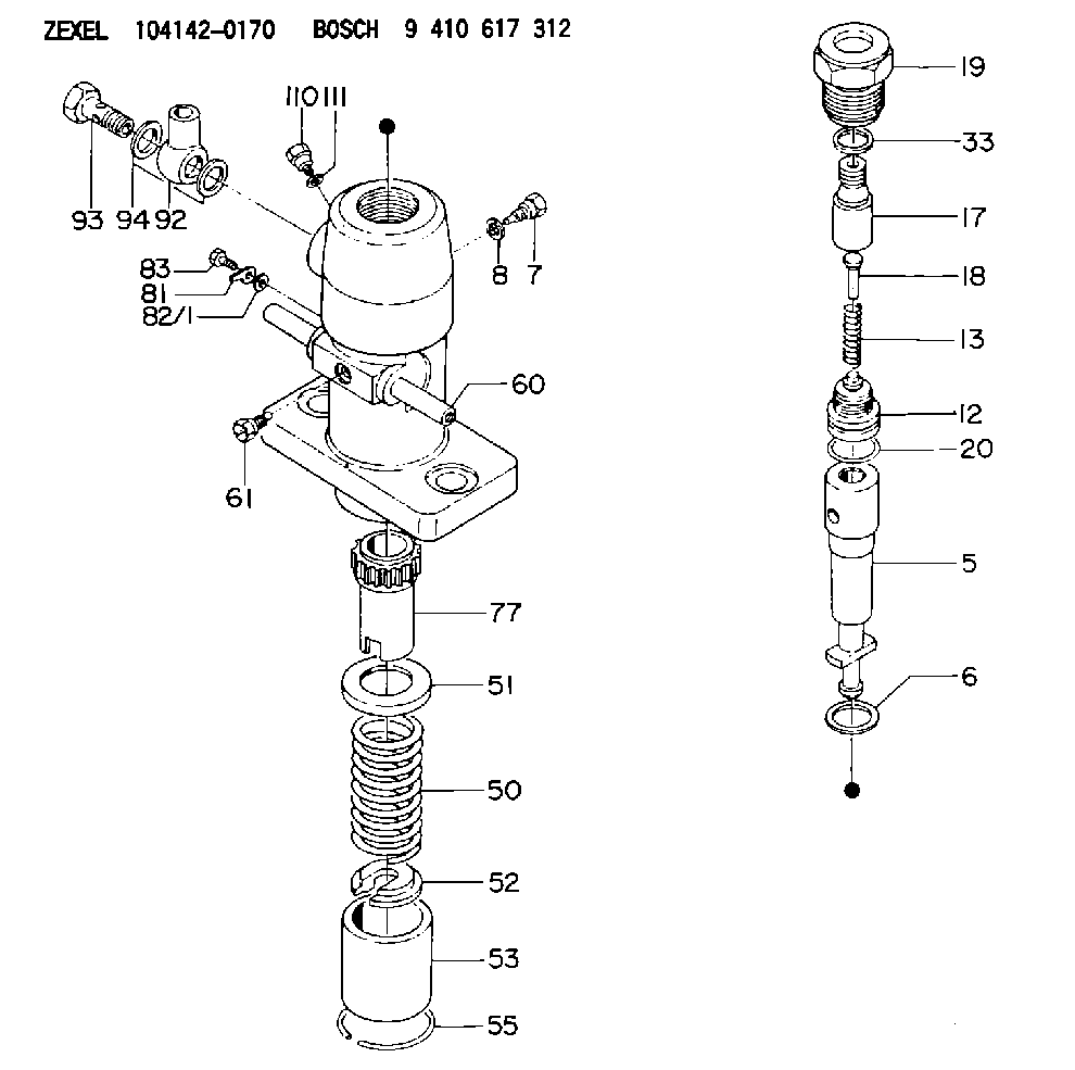
| 5. | [1] | 141170-1420 | PLUNGER-AND-BARREL ASSY |
| 6. | [1] | 029333-3010 | GASKET |
| 7. | [1] | 141106-8000 | CAPSULE |
| 8. | [1] | 029330-8050 | GASKET |
| 12. | [1] | 141110-2320 | DELIVERY-VALVE ASSEMBLY |
| 13. | [1] | 141112-0800 | COMPRESSION SPRING |
| 17. | [1] | 141136-9900 | FITTING |
| 18. | [1] | 141117-0400 | FILLER PIECE |
| 19. | [1] | 141119-0100 | NUT |
| 20. | [1] | 029633-2060 | O-RING |
| 33. | [1] | 141115-3800 | GASKET |
| 50. | [1] | 141215-3500 | COMPRESSION SPRING |
| 51. | [1] | 141216-0500 | SLOTTED WASHER |
| 52. | [1] | 141217-0300 | SLOTTED WASHER |
| 53. | [1] | 141218-4200 | GUIDE |
| 55. | [1] | 141220-0300 | LOCKING WASHER |
| 60. | [1] | 141230-8300 | CONTROL RACK |
| 61. | [1] | 141226-3100 | BLEEDER SCREW |
| 77. | [1] | 141241-0900 | CONTROL SLEEVE |
| 81. | [1] | 141245-2000 | POINTER |
| 82/1. | [0] | 023500-6210 | PLAIN WASHER D11&6.4T1.5 |
| 82/1. | [0] | 029300-6010 | PLAIN WASHER D11&6.4T0.8 |
| 82/1. | [0] | 029300-6020 | PLAIN WASHER D11&6.4T0.35 |
| 83. | [1] | 020006-1440 | BLEEDER SCREW M6P1L14 |
| 92. | [1] | 029701-8270 | INLET UNION |
| 93. | [1] | 029731-8200 | EYE BOLT |
| 94. | [2] | 026518-2240 | GASKET D21.9&18.2T1 |
| 110. | [1] | 140420-1800 | BLEEDER SCREW |
| 111. | [1] | 026506-1040 | GASKET D9.9&6.2T1 |
Cross reference number
Zexel num
Bosch num
Firm num
Name
104142-0170
2012604204 KUBOTA
FUEL-INJECTION PUMP
K 24DA FUEL INJECTION PUMP PF-1C(D) PF
K 24DA FUEL INJECTION PUMP PF-1C(D) PF
104142-0170
2012604206 KUBOTA
FUEL-INJECTION PUMP
A K 24DA FUEL INJECTION PUMP PF-1C(D) PF
A K 24DA FUEL INJECTION PUMP PF-1C(D) PF
104142-0170
2012604206 KUBOTA
FUEL-INJECTION PUMP
K 24DA FUEL INJECTION PUMP PF-1C(D) PF
K 24DA FUEL INJECTION PUMP PF-1C(D) PF
Information:
1. The customer must be asked many questions to determine whether his complaint is valid, or whether his diagnosis of an actual problem is correct.Some of the questions that must be asked are as follows:a Does poor performance occur when the vehicle is operated at steady speed on a level road surface, or when vehicle is pulled up a grade? A positive response to either or both of the above conditions would indicate a low power (steady state) problem. Begin with Low Power Diagnosis.b. Does the poor performance always occur under the same conditions or is the problem intermittent (happens only occasionally)? This is a very important line of questioning to pursue. Any constant performance problem can normally be identified and the problem corrected. If an intermittent problem exists, the mechanic must be aware that the condition is only occasional, and must run certain tests several times in an attempt to force the malfunction condition. If the condition is not duplicated, the diagnosis that no problem exists will be incorrect, and the vehicle operator will again be confronted with the problem somewhere out on the road.c. Was the engine running rough or misfiring when the poor performance was noticed? A positive response to this questions will indicate the need to isolate the bad cylinder(s) and correct the problem. See section Cylinder Misfire.2. Check the crankcase oil level and the coolant level of the radiator. Start the engine and get to normal operating temperature. A slightly lower rpm (15 rpm below low limit) should be expected for the engine in vehicle than the rpm shown in the Fuel Setting And Related Information Fiche. This is caused by the parasitic loads of the engine accessories involved.3. With the engine running, the throttle must have enough travel for the governor control lever to break over (go past the normal governor stop for high idle position) a small amount when the throttle pedal is fully depressed. If full travel is not available, disconnect throttle linkage from governor lever. With throttle linkage disconnected, full travel of governor lever will indicate linkage problems, and the linkage will have to be adjusted. Limited travel of the governor lever will indicate a problem within the governor.4. Only a mechanic with the correct training should change the set point (balance point). The procedure is given in the Service Manual under the subject Governor Adjustments.5. If the set point (balance point) cannot be made correct with the high idle adjustment screw, there is a problem inside the governor. Disassemble the governor and check for damaged parts or wrong parts installed in the governor. Some common problems are worn bushings, worn spring seat, or a broken or wrong governor spring.6. Before 8T0500 Circuit Tester is installed, be sure to test the light for correct operation. Test light must come on when the clip of the wire is placed against the probe of the light (replace batteries or bulb if light does not come on). If light comes on