Information fuel-injection pump
BOSCH
9 410 617 564
9410617564
ZEXEL
104141-3260
1041413260
Rating:
Components :
| 0. | INJECTION-PUMP ASSEMBLY | 104141-3260 |
| 1. | _ | |
| 2. | FUEL INJECTION PUMP | |
| 3. | NUMBER PLATE | |
| 4. | _ | |
| 5. | CAPSULE | |
| 6. | ADJUSTING DEVICE | |
| 7. | NOZZLE AND HOLDER ASSY | |
| 8. | Nozzle and Holder | |
| 9. | Open Pre:MPa(Kqf/cm2) | |
| 10. | NOZZLE-HOLDER | |
| 11. | NOZZLE |
Scheme ###:
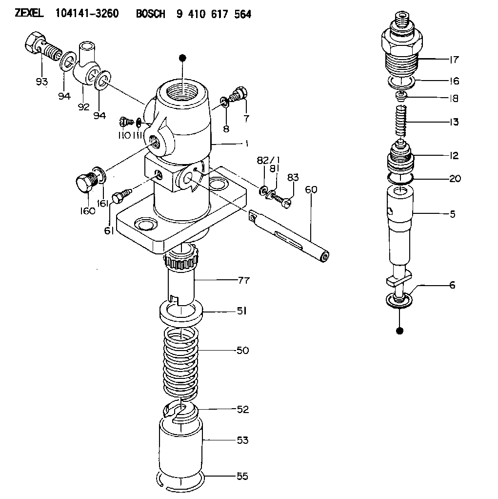
| 1. | [1] | 141054-3100 | PUMP HOUSING |
| 5. | [1] | 141175-0220 | PLUNGER-AND-BARREL ASSY |
| 6. | [1] | 029333-3010 | GASKET |
| 7. | [1] | 141133-3100 | CAPSULE |
| 8. | [1] | 029331-8010 | GASKET |
| 12. | [1] | 141110-5320 | DELIVERY-VALVE ASSEMBLY |
| 13. | [1] | 141112-0600 | COMPRESSION SPRING |
| 16. | [1] | 141115-6100 | GASKET |
| 17. | [1] | 141136-3800 | FITTING |
| 18. | [1] | 141117-3400 | SLOTTED WASHER |
| 20. | [1] | 029633-2040 | O-RING |
| 50. | [1] | 141215-0700 | COMPRESSION SPRING |
| 51. | [1] | 141216-2400 | SLOTTED WASHER |
| 52. | [1] | 141217-0300 | SLOTTED WASHER |
| 53. | [1] | 141218-4200 | GUIDE |
| 55. | [1] | 141220-0300 | LOCKING WASHER |
| 60. | [1] | 141223-9600 | CONTROL RACK |
| 61. | [1] | 141226-3000 | BLEEDER SCREW |
| 77. | [1] | 141241-6200 | CONTROL SLEEVE |
| 81. | [1] | 141245-2000 | POINTER |
| 82/1. | [0] | 023500-6210 | PLAIN WASHER D11&6.4T1.5 |
| 82/1. | [0] | 029300-6010 | PLAIN WASHER D11&6.4T0.8 |
| 82/1. | [0] | 029300-6020 | PLAIN WASHER D11&6.4T0.35 |
| 83. | [1] | 020006-1440 | BLEEDER SCREW M6P1L14 |
| 92. | [1] | 027118-1540 | INLET UNION |
| 93. | [1] | 029731-8200 | EYE BOLT |
| 94. | [2] | 141403-0400 | GASKET |
| 94. | [2] | 141403-0400 | GASKET |
| 110. | [1] | 140420-1600 | BLEEDER SCREW |
| 111. | [1] | 141421-0000 | GASKET |
| 160. | [1] | 029111-8090 | CAPSULE |
| 161. | [1] | 141403-0400 | GASKET |
Include in #1:
106873-7580
as _
Include in #2:
104141-3260
as INJECTION-PUMP ASSEMBLY
Cross reference number
Zexel num
Bosch num
Firm num
Name
104141-3260
9 410 617 564
FUEL-INJECTION PUMP
* K
* K
Information:
Delco-Remy Alternator
(1) Regulator. (2) Roller bearing. (3) Stator winding. (4) Ball bearing. (5) Rectifier bridge. (6) Field winding. (7) Rotor assembly. (8) Fan.Alternator (Bosch)
The alternator is driven by V-belts from the crankshaft pulley. This alternator is a three phrase, self-rectifying charging unit, and the regulator is part of the alternator.The 7N9720 Alternator has an output of 37A. The 9W3043 Alternator has an output of 40A.
Bosch Alternator
(1) Fan. (2) Stator winding. (3) Field winding. (4) Regulator. (5) Ball bearing. (6) Roller bearing. (7) Rotor. (8) Rectifier assembly.This alternator design has no need for slip rings or brushes, and the only part that has movement is the rotor assembly. All conductors that carry current are stationary. The conductors are: the field winding, stator windings, six rectifying diodes, and the regulator circuit components.The rotor assembly has many magnetic poles like fingers with air space between each opposite pole. The poles have residual magnetism (like permanent magnets) that produce a small amount of magnet-like lines of force (magnetic field) between the poles. As the rotor assembly begins to turn between the field winding and the stator windings, a small amount of alternating current (AC) is produced in the stator windings from the small magnetic lines of force made by the residual magnetism of the poles. This AC current is changed to direct current (DC) when it passes through the diodes of the rectifier bridge. Most of this current goes to charge the battery and to supply the low amperage circuit, and the remainder is sent to the field windings. The DC current flow through the field windings (wires around an iron core) now increases the strength of the magnetic lines of force. These stronger lines of force now increase the amount of AC current produced in the stator windings. The increased speed of the rotor assembly also increases the current and voltage output of the alternator.Alternator (Nippondenso)
The Nippondenso alternator has three-phase, full-wave rectified output. It is brushless. The rotor and bearings are the only moving parts. There is a 24 volt, 9G4574 Alternator with 35 amp output and a 12 volt, 8T9900 Alternator with a 55 amp output.
9G4574 Nippondenso Alternator
(1) Fan. (2) Front frame assembly. (3) Stator assembly. (4) Rotor assembly. (5) Field winding (coil assembly). (6) Regulator assembly. (7) Condenser (suppression capacitor). (8) Rectifier assembly. (9) Rear frame assembly.When the engine is started and the rotor turns inside the stator windings, three-phase alternating current (AC) and rapidly rising voltage is generated.A small amount of alternating current (AC) is changed (rectified) to pulsating direct current (DC) by the exciter diodes on the rectifier assembly. Output current from these diodes adds to the initial current which flows through the rotor field windings from residual magnetism. This will make the rotor a stronger magnet and cause the alternator to become activated automatically. As rotor speed, current and voltages increase, the rotor field current increases enough until the alternator becomes fully activated.The main battery charging current is charged (rectified) from AC to DC by the
Have questions with 104141-3260?
Group cross 104141-3260 ZEXEL
Daihatsu
104141-3260
9 410 617 564
FUEL-INJECTION PUMP