Information fuel-injection pump
BOSCH
9 410 617 558
9410617558
ZEXEL
104140-8042
1041408042
DAIHATSU
E186450050ZZ
e186450050zz
Rating:
Components :
| 0. | INJECTION-PUMP ASSEMBLY | 104140-8042 |
| 1. | _ | |
| 2. | FUEL INJECTION PUMP | |
| 3. | NUMBER PLATE | |
| 4. | _ | |
| 5. | CAPSULE | |
| 6. | ADJUSTING DEVICE | |
| 7. | NOZZLE AND HOLDER ASSY | |
| 8. | Nozzle and Holder | |
| 9. | Open Pre:MPa(Kqf/cm2) | |
| 10. | NOZZLE-HOLDER | |
| 11. | NOZZLE |
Scheme ###:
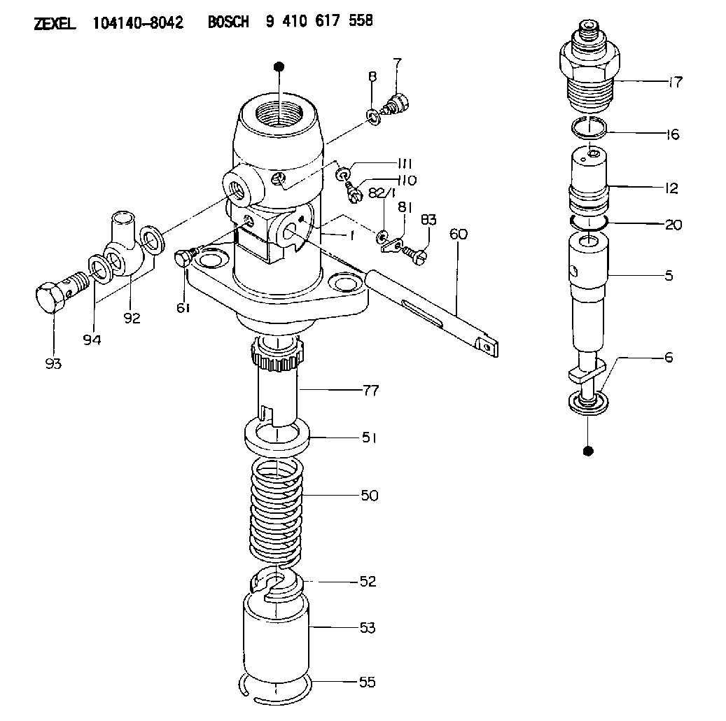
| 1. | [1] | 141052-7201 | PUMP HOUSING |
| 5. | [1] | 141170-4620 | PLUNGER-AND-BARREL ASSY |
| 6. | [1] | 029333-3010 | GASKET |
| 7. | [1] | 141133-3100 | CAPSULE |
| 8. | [1] | 029331-8010 | GASKET |
| 12. | [1] | 141142-6221 | DELIVERY-VALVE ASSEMBLY |
| 16. | [1] | 141115-6000 | GASKET |
| 17. | [1] | 141136-6400 | FITTING |
| 20. | [1] | 029633-2040 | O-RING |
| 50. | [1] | 141215-0700 | COMPRESSION SPRING |
| 51. | [1] | 141216-2400 | SLOTTED WASHER |
| 52. | [1] | 141217-0300 | SLOTTED WASHER |
| 53. | [1] | 141218-4500 | GUIDE |
| 55. | [1] | 141220-0300 | LOCKING WASHER |
| 60. | [1] | 142223-0200 | CONTROL RACK |
| 61. | [1] | 141226-3000 | BLEEDER SCREW |
| 77. | [1] | 141241-6200 | CONTROL SLEEVE |
| 81. | [1] | 141245-2000 | POINTER |
| 82/1. | [0] | 023500-6210 | PLAIN WASHER D11&6.4T1.5 |
| 82/1. | [0] | 029300-6010 | PLAIN WASHER D11&6.4T0.8 |
| 82/1. | [0] | 029300-6020 | PLAIN WASHER D11&6.4T0.35 |
| 83. | [1] | 020006-1440 | BLEEDER SCREW M6P1L14 |
| 92. | [1] | 027118-1540 | INLET UNION |
| 93. | [1] | 029731-8200 | EYE BOLT |
| 94. | [2] | 141403-0400 | GASKET |
| 110. | [1] | 140420-1600 | BLEEDER SCREW |
| 111. | [1] | 141421-0000 | GASKET |
Include in #1:
101608-6060
as _
Include in #2:
104140-8042
as INJECTION-PUMP ASSEMBLY
Cross reference number
Zexel num
Bosch num
Firm num
Name
104140-8042
E186450050ZZ DAIHATSU
FUEL-INJECTION PUMP
K 24DA FUEL INJECTION PUMP PF-1C(D) PF
K 24DA FUEL INJECTION PUMP PF-1C(D) PF
104140-8042
E186450050ZZ DAIHATSU
FUEL-INJECTION PUMP
K 24DA FUEL INJECTION PUMP PF-1C(D) PF
K 24DA FUEL INJECTION PUMP PF-1C(D) PF
Information:
1. Locate top center (TC) compressing stroke for No. 1 piston. See LOCATING TOP CENTER COMPRESSION POSITION FOR NO. 1 PISTON in TESTING AND ADJUSTING. 2. Install the timing fixture plate (A), on the rear face of the accessory drive shaft housing.3. If the plate can be installed with the dowels in the accessory drive shaft housing aligned with the dowel holes in the plate, the accessory drive shaft is correctly timed. Proceed to Step 8. If the plate cannot be installed, continue with Step 4. 4. Remove the cover (1) from the front of the timing gear cover. Remove the accessory drive gear retaining nut and washer. 5. Using tool (B), separate the gear from the accessory drive shaft. Rotate the accessory drive shaft until the timing fixture plate (A) can be installed.6. Install the conical washer on the drive shaft with the O.D. in contact with the gear. Install and tighten the retaining nut to 100 10 lb. ft. (13,8 1,4 mkg). 7. Install the cover (1) on the timing gear cover, and remove the timing fixture plate.8. Position the fuel injection pump housing and governor on the engine, and install the mounting bolts.9. Connect the fuel injection lines and tighten the retaining nut to 30 5 lb. ft. (4,1 0,7 mkg).10. Connect the fuel ratio control sensing line.11. Connect the turbocharger oil supply line and clamp.12. Connect the governor control linkage.
When the governor control linkage is connected the spring tension must hold the governor control lever towards the OFF position.
Separate Governor From Fuel Injection Pump Housing
preparatory steps: a) remove fuel injection pump housing and governor as a unitb) remove fuel ratio control1. Remove idle screw housing plate assembly, and shut down solenoid. 2. Remove two retaining bolts (3) and remove the solenoid fuel shutoff lever (4).3. Remove the idle screw cover (1).4. Remove idle screw housing (2).5. Remove the rack stop collar retaining screw (7). 6. Remove the rack stop collar (5), collar (8), and spring (6).7. Remove the governor-to-fuel injection pump housing mounting bolts (9). 8. Remove the governor housing (10).9. Remove the governor spring (13), seat assembly (11), and washer-type spring. 10. Remove the three mounting bolts (12) and lock that secure the cylinder and weight assemblies (14) to the fuel injection pump housing.11. Pull the cylinder and weight assemblies straight out to clear locating dowels.12. Move the cylinder and weight assemblies sideways to disengage slot in piston from the rack (15).Connect Governor To Fuel Injection Pump Housing
1. Position the cylinder and weight assemblies (1) on the fuel injection pump housing so slot in piston is engaged with the rack (2).2. Push the cylinder and weight assemblies onto the locating dowels. 3. Install the three mounting bolts (5) and lock.4. Install the washer-type spring, seat assembly (4), and governor spring (6) on the cylinder assembly. The washer-type spring should be installed so the outside diameter of spring will contact the guide in governor housing (3).5. Position the governor housing