Information fuel-injection pump
BOSCH
9 410 617 557
9410617557
ZEXEL
104140-8021
1041408021
DAIHATSU
332888
332888

Rating:
Components :
| 0. | INJECTION-PUMP ASSEMBLY | 104140-8021 |
| 1. | _ | |
| 2. | FUEL INJECTION PUMP | |
| 3. | NUMBER PLATE | |
| 4. | _ | |
| 5. | CAPSULE | |
| 6. | ADJUSTING DEVICE | |
| 7. | NOZZLE AND HOLDER ASSY | |
| 8. | Nozzle and Holder | |
| 9. | Open Pre:MPa(Kqf/cm2) | |
| 10. | NOZZLE-HOLDER | |
| 11. | NOZZLE |
Scheme ###:
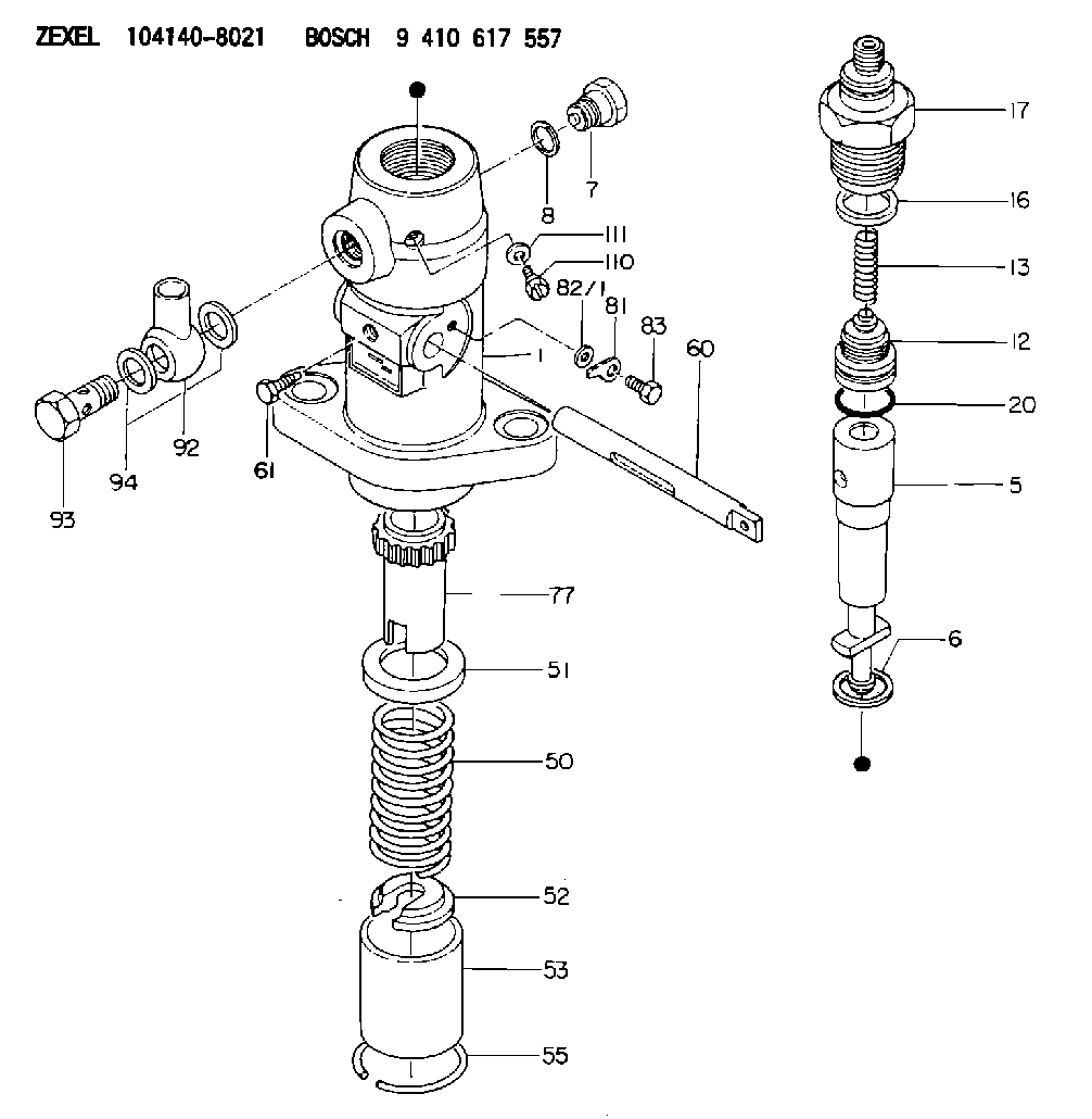
| 1. | [1] | 141052-7201 | PUMP HOUSING |
| 5. | [1] | 141170-0020 | PLUNGER-AND-BARREL ASSY |
| 6. | [1] | 029333-3010 | GASKET |
| 7. | [1] | 141133-3100 | CAPSULE |
| 8. | [1] | 029331-8010 | GASKET |
| 12. | [1] | 141110-5320 | DELIVERY-VALVE ASSEMBLY |
| 13. | [1] | 141112-0600 | COMPRESSION SPRING |
| 16. | [1] | 141115-6100 | GASKET |
| 17. | [1] | 141136-1120 | FITTING |
| 20. | [1] | 029633-2040 | O-RING |
| 50. | [1] | 141215-0700 | COMPRESSION SPRING |
| 51. | [1] | 141216-2400 | SLOTTED WASHER |
| 52. | [1] | 141217-0300 | SLOTTED WASHER |
| 53. | [1] | 141218-4500 | GUIDE |
| 55. | [1] | 141220-0300 | LOCKING WASHER |
| 60. | [1] | 142223-0200 | CONTROL RACK |
| 61. | [1] | 141226-3000 | BLEEDER SCREW |
| 77. | [1] | 141241-0900 | CONTROL SLEEVE |
| 81. | [1] | 141245-2000 | POINTER |
| 82/1. | [0] | 023500-6210 | PLAIN WASHER D11&6.4T1.5 |
| 82/1. | [0] | 029300-6010 | PLAIN WASHER D11&6.4T0.8 |
| 82/1. | [0] | 029300-6020 | PLAIN WASHER D11&6.4T0.35 |
| 83. | [1] | 020006-1440 | BLEEDER SCREW M6P1L14 |
| 92. | [1] | 027118-1540 | INLET UNION |
| 93. | [1] | 029731-8200 | EYE BOLT |
| 94. | [2] | 141403-0400 | GASKET |
| 110. | [1] | 140420-1600 | BLEEDER SCREW |
| 111. | [1] | 141421-0000 | GASKET |
Include in #1:
101608-6030
as _
Include in #2:
104140-8021
as INJECTION-PUMP ASSEMBLY
Cross reference number
Zexel num
Bosch num
Firm num
Name
104140-8021
332888 DAIHATSU
FUEL-INJECTION PUMP
K 24DA FUEL INJECTION PUMP PF-1C(D) PF
K 24DA FUEL INJECTION PUMP PF-1C(D) PF
104140-8021
332888 DAIHATSU
FUEL-INJECTION PUMP
K 24DA FUEL INJECTION PUMP PF-1C(D) PF
K 24DA FUEL INJECTION PUMP PF-1C(D) PF
Information:
Bolts And Bolt Torque
A bolt which is too long may "bottom" before the head is tight against the part it is to hold. The threads can be damaged when a "long" bolt is removed.If a bolt is too short, there may not be enough threads engaged to hold the part securely.Apply proper torque values to all bolts and nuts when assembling Caterpillar equipment. When a specific torque value is required, the value is listed in the SPECIFICATIONS section of the Service Manual. Tighten all other bolts and nuts for general usage, hydraulic valve bodies, or taperlock studs to the torque values given in the torque charts.T-T-T Procedure
A torque-turn-tighten (T-T-T) procedure is used in many specifications and instructions.1. Clean the bolt and nut threads.2. Put lubricant on the threads and the seat face of the bolt and the nut.3. Turn the bolt or the nut tight according to the torque specification.4. Put a location mark on the part and on the bolt or the nut.5. Turn the bolt or the nut tighter the amount of degrees according to the specifications. The side of a nut or bolt head can be used for reference if a mark can not be put on. Torque Wrench Extension
When a torque wrench extension is used with a torque wrench, the torque indication on the torque wrench will be less than the real torque.
TORQUE WRENCH WITH TORQUE WRENCH EXTENSION
E: Torque wrench drive axis-to-torque wrench extension drive axis. W: Mark on handle-to-torque wrench drive axis.1. Put a mark on the handle. Measure the handle from the mark to the axis of the torque wrench drive (W).2. Measure the torque wrench extension from the torque wrench drive to the axis of the torque wrench extension drive (E).3. To get correct torque indication (TI) when the real torque (RT) is known: Example: W = 12 in. (304.8 mm); E = 2.56 in. (65.0 mm); RT (from specifications) = 125 lb. ft. (170 N m). 4. Hold the torque wrench handle with the longest finger of the hand over the mark on the handle to get the real torque (RT) with low torque indication (TI) on the torque wrench.Locks
Flat metal locks must be installed properly to be effective. Bend one end of the lock around the edge of the part. Bend the other end against one flat surface of the nut or bolt head.Always install new locks in compartments which house moving parts.If lockwashers are installed on housings made of aluminum, use a flat washer between the lockwasher and the housing. Lines And Wires
When removing or disconnecting a group of lines or wires, tag each one to assure proper assembly.Lubrication
Where applicable, fill the compartments of the components serviced with the amount, type and grade of lubricant recommended in the Lubrication and Maintenance Guide.Rust Preventive Compound
Clean the rust preventive compound from all machined surfaces of new parts before installing them.Shims
When shims are removed, tie them together and identify them as to location. Keep shims clean and flat until they are