Information fuel-injection pump
BOSCH
9 410 617 069
9410617069
ZEXEL
104140-8010
1041408010
DAIHATSU
E186200030A
e186200030a
Rating:
Components :
| 0. | INJECTION-PUMP ASSEMBLY | 104140-8010 |
| 1. | _ | |
| 2. | FUEL INJECTION PUMP | |
| 3. | NUMBER PLATE | |
| 4. | _ | |
| 5. | CAPSULE | |
| 6. | ADJUSTING DEVICE | |
| 7. | NOZZLE AND HOLDER ASSY | |
| 8. | Nozzle and Holder | |
| 9. | Open Pre:MPa(Kqf/cm2) | |
| 10. | NOZZLE-HOLDER | |
| 11. | NOZZLE | 105011-9270 |
Scheme ###:
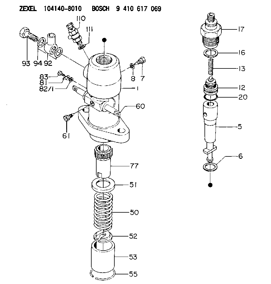
| 1. | [1] | 141052-3000 | PUMP HOUSING |
| 5. | [1] | 141170-0020 | PLUNGER-AND-BARREL ASSY |
| 6. | [1] | 029333-3010 | GASKET |
| 7. | [1] | 141106-8000 | CAPSULE |
| 8. | [1] | 029330-8050 | GASKET |
| 12. | [1] | 141140-1320 | DELIVERY-VALVE ASSEMBLY |
| 13. | [1] | 141112-0600 | COMPRESSION SPRING |
| 16. | [1] | 141115-6100 | GASKET |
| 17. | [1] | 141136-1120 | FITTING |
| 20. | [1] | 029633-2040 | O-RING |
| 50. | [1] | 141215-0700 | COMPRESSION SPRING |
| 51. | [1] | 141216-2400 | SLOTTED WASHER |
| 52. | [1] | 141217-0300 | SLOTTED WASHER |
| 53. | [1] | 141218-4500 | GUIDE |
| 55. | [1] | 141220-0300 | LOCKING WASHER |
| 60. | [1] | 141223-3100 | CONTROL RACK |
| 61. | [1] | 141226-3100 | BLEEDER SCREW |
| 77. | [1] | 141241-0900 | CONTROL SLEEVE |
| 81. | [1] | 141245-2000 | POINTER |
| 82/1. | [0] | 023500-6210 | PLAIN WASHER D11&6.4T1.5 |
| 82/1. | [0] | 029300-6010 | PLAIN WASHER D11&6.4T0.8 |
| 82/1. | [0] | 029300-6020 | PLAIN WASHER D11&6.4T0.35 |
| 83. | [1] | 020006-1440 | BLEEDER SCREW M6P1L14 |
| 92. | [1] | 027118-1540 | INLET UNION |
| 93. | [1] | 029731-8200 | EYE BOLT |
| 94. | [2] | 026518-2240 | GASKET D21.9&18.2T1 |
| 110. | [1] | 141420-1320 | BLEEDER SCREW |
| 111. | [1] | 026512-1540 | GASKET D15.4&12.2T1.50 |
Include in #1:
101608-6010
as _
Include in #2:
104140-8010
as INJECTION-PUMP ASSEMBLY
Cross reference number
Zexel num
Bosch num
Firm num
Name
104140-8010
E186200030A DAIHATSU
FUEL-INJECTION PUMP
K 24DA FUEL INJECTION PUMP PF-1C(D) PF
K 24DA FUEL INJECTION PUMP PF-1C(D) PF
Information:
Shunt-Type Cooling System
A shunt-type cooling system for the engine is recommended. A shunt-type cooling system radiator has a normal top tank (9) above the radiator core (10) and an expansion tank (2) above (any location) the top tank.An air and coolant tube (7) allows excess air and coolant in the radiator top tank to flow into the expansion tank. The expansion tank has a shunt line (3) which connects to the water pump (11) inlet. The shunt system maintains a positive head of coolant at the pump inlet to prevent cavitation in the pump under all operating conditions.When initially filling the cooling system, the coolant in expansion tank (2) flows through shunt line (3) to the water pump inlet, flows through pump (11), and fills engine cylinder block (13) from the bottom. Coolant flowing into the bottom of the block forces the air out through the top of temperature regulator housing (4), through tube (7) into expansion tank (2).It is a good procedure, after filling the system, to immediately start the engine and make certain the cooling system is full after a few minutes of engine operation. The operating water pump circulates the coolant through the engine, to drive out any air that could have been trapped in the engine. It may be necessary to add more coolant to fill the system.
SHUNT-TYPE RADIATOR COOLING SYSTEM-SCHEMATIC (Temperature regulator partially open)
1-Radiator cap (pressure regulating valve). 2-Expansion tank. 3-Shunt line tube. 4-Temperature regulator (thermostat) housing. 5-Cylinder liners (six). 6-Cylinder head. 7-Air and coolant bleed tube (between radiator top tank and expansion tank). 8-Radiator coolant bypass tube. 9-Radiator top tank. 10-Radiator core. 11-Water pump. 12-Engine lubricating oil cooler. 13-Cylinder block.Cylinder Head
CYLINDER HEAD-END VIEW
1-Precombustion chamber (six). 2-Spring (twelve). 3-Lock (twenty four). 4-Rotocoil assembly (twelve). 5-Rocker arm (twelve). 6-Push rod (twelve). 7-Air inlet manifold (in head). 8-Valve seat insert (six inlet, six exhaust). 9-Valve (six inlet, six exhaust).This overhead valve (OHV) cylinder head has one inlet and one exhaust valve for each engine cylinder. Rocker arms (5) are operated by the camshaft, in the engine cylinder block, cam followers (lifters) and push rods (6) which open and close valves (9) at the proper time. Each rocker arm has an adjustable contact to obtain the recommended valve lash (valve clearance). Each valve spring (2), to close a valve, is retained by locks (3) and a rotocoil assembly (4). The rotocoil will rotate a valve stem approximately one third of a degree each time the valve opens and closes. This will rotate the valve about one revolution per minute when the engine is operating at full load RPM.The valve bushings (guides) and valve seat inserts (8) can be removed, if necessary, and new ones installed. The valve seats are ground at 30° angles. The high heat resistant steel inlet valves and stellite exhaust valves are gound slightly less (about one fourth of a degree) than 30° angles. The interference angles between the valves and valve seats provide for better seating for longer periods of time.The inlet