Information fuel-injection pump
BOSCH
9 410 617 309
9410617309
ZEXEL
104140-3120
1041403120
KUBOTA
1722667210
1722667210
Rating:
Components :
| 0. | INJECTION-PUMP ASSEMBLY | 104140-3120 |
| 1. | _ | |
| 2. | FUEL INJECTION PUMP | |
| 3. | NUMBER PLATE | |
| 4. | _ | |
| 5. | CAPSULE | |
| 6. | ADJUSTING DEVICE | |
| 7. | NOZZLE AND HOLDER ASSY | |
| 8. | Nozzle and Holder | |
| 9. | Open Pre:MPa(Kqf/cm2) | |
| 10. | NOZZLE-HOLDER | |
| 11. | NOZZLE |
Scheme ###:
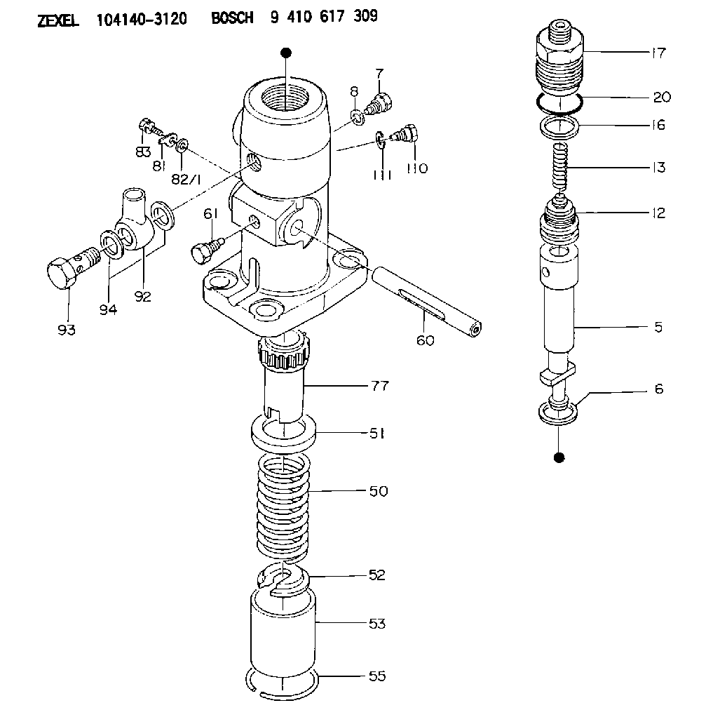
| 5. | [1] | 141170-0020 | PLUNGER-AND-BARREL ASSY |
| 6. | [1] | 029333-3010 | GASKET |
| 7. | [1] | 141106-8000 | CAPSULE |
| 8. | [1] | 029340-8020 | GASKET |
| 12. | [1] | 141142-0920 | DELIVERY-VALVE ASSEMBLY |
| 13. | [1] | 141112-0300 | COMPRESSION SPRING |
| 16. | [1] | 141115-4400 | GASKET |
| 17. | [1] | 141136-8620 | FITTING |
| 20. | [1] | 029633-2040 | O-RING |
| 50. | [1] | 141215-1900 | COMPRESSION SPRING |
| 51. | [1] | 141216-2400 | SLOTTED WASHER |
| 52. | [1] | 141217-1500 | SLOTTED WASHER |
| 53. | [1] | 141218-4200 | GUIDE |
| 55. | [1] | 141220-0300 | LOCKING WASHER |
| 60. | [1] | 141230-8300 | CONTROL RACK |
| 61. | [1] | 141226-3100 | BLEEDER SCREW |
| 77. | [1] | 141241-0900 | CONTROL SLEEVE |
| 81. | [1] | 141245-2000 | POINTER |
| 82/1. | [0] | 023500-6210 | PLAIN WASHER D11&6.4T1.5 |
| 82/1. | [0] | 029300-6010 | PLAIN WASHER D11&6.4T0.8 |
| 82/1. | [0] | 029300-6020 | PLAIN WASHER D11&6.4T0.35 |
| 83. | [1] | 020006-1440 | BLEEDER SCREW M6P1L14 |
| 92. | [1] | 027118-1540 | INLET UNION |
| 93. | [1] | 029731-8200 | EYE BOLT |
| 94. | [2] | 026518-2240 | GASKET D21.9&18.2T1 |
| 110. | [1] | 140420-1800 | BLEEDER SCREW |
| 111. | [1] | 026506-1040 | GASKET D9.9&6.2T1 |
Include in #1:
101608-1980
as _
Include in #2:
104140-3120
as INJECTION-PUMP ASSEMBLY
Cross reference number
Zexel num
Bosch num
Firm num
Name
Information:
MAIN BEARINGS
1. Bolt (partially hidden under oil pump). 2. Front cover. 3. Oil pump. 4. Bolts (two per cap). 5. Main bearing cap.
ADAPTER
6. 8S5131 Adpater.4. Use a commercially available bearing removal tool to roll out upper halves of main bearings.Install Main Bearings
1. Use a commercially available bearing removal tool to install the upper halves of the main bearings. Lubricate with clean engine oil (SAE 30) before installing. The main bearing half with the oil hole is the upper half. Be sure to install correctly.2. Lubricate lower halves of main bearings with engine oil (SAE 30). Install main bearing caps (5) so number on cap corresponds with number on saddle of cylinder block. Both numbers must be on same side of block.3. Put engine oil on the threads of the bolts and the face of the washers and install bolts (4) into the cylinder block.4. Use adapter (6) to install bolt (1) when front cover (2) and oil pump (3) are mounted on cylinder block. For 1140 (36B1-36B1923), 1145 (97B1-97B6154), 1150 (96B1-96B6580), 1160 (95B1-95B13691) Engines, install bolt (1) using a 9S7353 Torque Wrench with an 8S5131 Adapter. Do not tighten bolt (1) at this time. Tighten bolt (1) in the number sequence shown with the other bolts but tighten it to a first torque of 48 lb. ft. (6.6 mkg) and a last torque of 140 lb. ft. (19.4 mkg). See Step 5 for torque of the other bolts.For 1140 (36B1924-Up), 1145 (97B6155-Up), 1150 (96B6581-Up), 1160 (95B13692-Up) Engines, install bolt (1) using a 9S7353 Torque Wrench with an 8S5131 Adapter. Do not tighten bolt (1) at this time. Tighten bolt (1) in the number sequence shown with the other bolts but tighten it to a first torque of 24 lb. ft. (3.3 mkg). Put a mark on the bolt and cap. Tighten the bolt an added 120° 5° from the mark. See Step 6 for torque of the other bolts.
MAIN BEARINGS
1. Bolt (partially hidden under oil pump). 2. Front cover. 3. Oil pump. 4. Bolts (two per cap). 5. Main bearing cap.
ADAPTER
6. 8S5131 Adapter.5. Tighten the bolts for the main bearing caps in the number sequence shown to a first torque of 60 15 lb. ft. (8.3 2.1 mkg). Tighten all bolts in the number sequence shown (hand torque only) to a last torque of 175 10 lb. ft. (24.2 1.4 mkg).
BOLT TIGHTENING SEQUENCE6. Tighten the bolts for the main bearing caps in the number sequence shown to a first torque of 30 3 lb. ft. (4.1 0.4 mkg). Put a mark on each bolt and cap and tighten, in the number sequence shown, an added 120° 5° from the mark.