Information fuel-injection pump
BOSCH
9 410 617 214
9410617214
ZEXEL
104140-3071
1041403071
DAIHATSU
C26640336195
c26640336195
Rating:
Components :
| 0. | INJECTION-PUMP ASSEMBLY | 104140-3071 |
| 1. | _ | |
| 2. | FUEL INJECTION PUMP | |
| 3. | NUMBER PLATE | |
| 4. | _ | |
| 5. | CAPSULE | |
| 6. | ADJUSTING DEVICE | |
| 7. | NOZZLE AND HOLDER ASSY | 105103-3170 |
| 8. | Nozzle and Holder | |
| 9. | Open Pre:MPa(Kqf/cm2) | 26.5{270} |
| 10. | NOZZLE-HOLDER | 105033-6020 |
| 11. | NOZZLE | 105011-9270 |
Scheme ###:
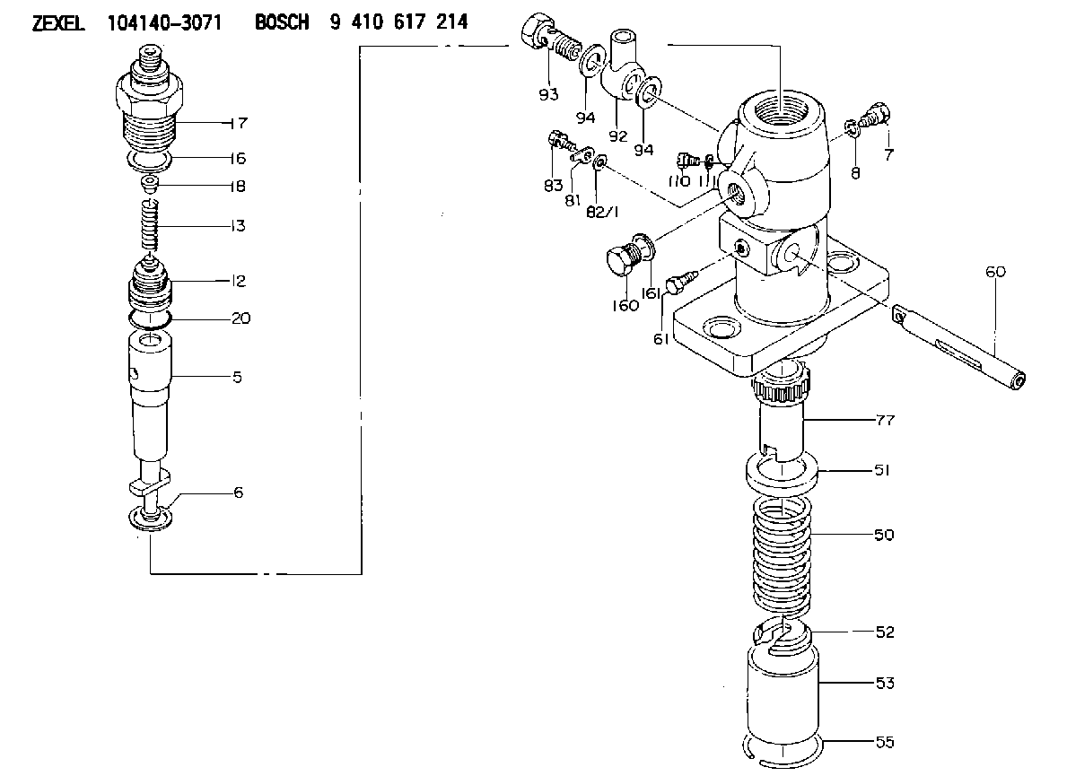
| 1. | [1] | 141052-7601 | PUMP HOUSING |
| 5. | [1] | 141175-0420 | PLUNGER-AND-BARREL ASSY |
| 6. | [1] | 029333-3010 | GASKET |
| 7. | [1] | 141133-3100 | CAPSULE |
| 8. | [1] | 029331-8010 | GASKET |
| 12. | [1] | 141110-5320 | DELIVERY-VALVE ASSEMBLY |
| 13. | [1] | 141112-0600 | COMPRESSION SPRING |
| 16. | [1] | 141115-6100 | GASKET |
| 17. | [1] | 141136-3800 | FITTING |
| 18. | [1] | 141117-3400 | SLOTTED WASHER |
| 20. | [1] | 029633-2040 | O-RING |
| 50. | [1] | 141215-0700 | COMPRESSION SPRING |
| 51. | [1] | 141216-2400 | SLOTTED WASHER |
| 52. | [1] | 141217-0300 | SLOTTED WASHER |
| 53. | [1] | 141218-4200 | GUIDE |
| 55. | [1] | 141220-0300 | LOCKING WASHER |
| 60. | [1] | 141223-9600 | CONTROL RACK |
| 61. | [1] | 141226-3000 | BLEEDER SCREW |
| 77. | [1] | 141241-6200 | CONTROL SLEEVE |
| 81. | [1] | 141245-2000 | POINTER |
| 82/1. | [0] | 023500-6210 | PLAIN WASHER D11&6.4T1.5 |
| 82/1. | [0] | 029300-6010 | PLAIN WASHER D11&6.4T0.8 |
| 82/1. | [0] | 029300-6020 | PLAIN WASHER D11&6.4T0.35 |
| 83. | [1] | 020006-1440 | BLEEDER SCREW M6P1L14 |
| 92. | [1] | 027118-1540 | INLET UNION |
| 93. | [1] | 029731-8200 | EYE BOLT |
| 94. | [2] | 141403-0400 | GASKET |
| 94. | [2] | 141403-0400 | GASKET |
| 110. | [1] | 140420-1600 | BLEEDER SCREW |
| 111. | [1] | 141421-0000 | GASKET |
| 160. | [1] | 029111-8090 | CAPSULE |
| 161. | [1] | 141403-0400 | GASKET |
Include in #1:
101608-1920
as _
Include in #2:
104140-3071
as INJECTION-PUMP ASSEMBLY
Cross reference number
Zexel num
Bosch num
Firm num
Name
Information:
TIMING MARKS2. Remove the plug from the timing pin hole in fuel injection pump housing and install timing pin (1).
TIMING PIN INSTALLED
1. FT887 Timing Pin (Fabricated Tool).3. Remove the tachometer drive adapter shaft (2).
TACHOMETER DRIVE ADAPTER
2. Tachometer drive adapter shaft.4. Using puller group (3), remove the fuel injection pump camshaft drive gear as follows. Thread the 9S8528 Bolt Assembly into the fuel injection pump camshaft. Do not force the bolt assembly. It should thread easily. Install the 9S8527 Bolt by threading it into the drive gear. Then tighten the 9S8527 Bolt with a wrench until the gear "pops" loose. Remove the gear (4) and the tool setup.
9S8520 PULLER GROUP INSTALLED
3. 9S8520 Puller Group.
REMOVING GEAR
4. Gear.5. Remove retaining screw (5), washer (6), and automatic timing advance (7) from the engine camshaft.
TIMING ADVANCE
5. Retaining screw. 6. Washer. 7. Automatic timing advance.6. Install puller (8), with spacer (10) over the shaft in the camshaft and spacer (9) on spacer (10) as shown and remove the gear from the camshaft.
REMOVING GEAR (Typical Example)
8. 1P2321 Puller. 9. 8S5579 Spacer. 10. 9S9155 Spacer.Install Camshaft Gear
1. Heat the gear to a temperature of approximately 400° F (204° C) before installing on the camshaft.
Do not heat the gear with a torch. Do not heat the gear to a temperature of more than 600° F (315° C). Heating the gear with a torch or to a temperature of more than 600° F (315° C) may cause the two drive dowels for the automatic timing advance to loosen and come out of the gear.
2. Align slot in gear hub with the pin in the camshaft. Install the gear on the camshaft with timing mark on gear aligned with timing mark on crankshaft gear. Be sure the gear is completely seated against the shoulder of the camshaft.
TIMING MARKS
Do not drive the gear on the camshaft. Serious damage can result to camshaft or camshaft thrust pin.
3. Align holes in weights with dowels in gear and install the automatic timing advance.4. Align pin (11) in washer (6) with hole (12) in camshaft and install washer (6).
INSTALLING WASHER
6. Washer. 11. Pin. 12. Hole.5. Install retaining screw (5) and tighten to 108 36 lb. in. (124.5 41.5 cm.kg). Stake screw (5) in two places.
Stake retaining screw (5) carefully. Heavy blows on washer or retaining screw can force the shaft extension too far into the camshaft and eliminate all end clearance.
STAKING SCREW (Typical Example)
5. Retaining screw.6. After retaining screw (5) is staked, the gear and weight assembly requires .003 to .027 in. (0.08 to 0.69 mm) end clearance to prevent binding against the washer, camshaft end, or camshaft gear.7. Position the drive gear on the fuel injection pump camshaft.8. Install the tachometer drive adapter shaft and tighten the shaft retaining nut to 32 2 lb. ft. (4.4 0.3 mkg).9. Remove the timing pin from the fuel injection pump housing and install the plug in the timing hole.