Information fuel-injection pump
BOSCH
9 410 617 556
9410617556
ZEXEL
104140-3061
1041403061
DAIHATSU
C26640336192Z
c26640336192z
Rating:
Components :
| 0. | INJECTION-PUMP ASSEMBLY | 104140-3061 |
| 1. | _ | |
| 2. | FUEL INJECTION PUMP | |
| 3. | NUMBER PLATE | |
| 4. | _ | |
| 5. | CAPSULE | |
| 6. | ADJUSTING DEVICE | |
| 7. | NOZZLE AND HOLDER ASSY | 105123-5320 |
| 8. | Nozzle and Holder | |
| 9. | Open Pre:MPa(Kqf/cm2) | 21.6{220} |
| 10. | NOZZLE-HOLDER | 105053-6030 |
| 11. | NOZZLE | 105011-7260 |
Scheme ###:
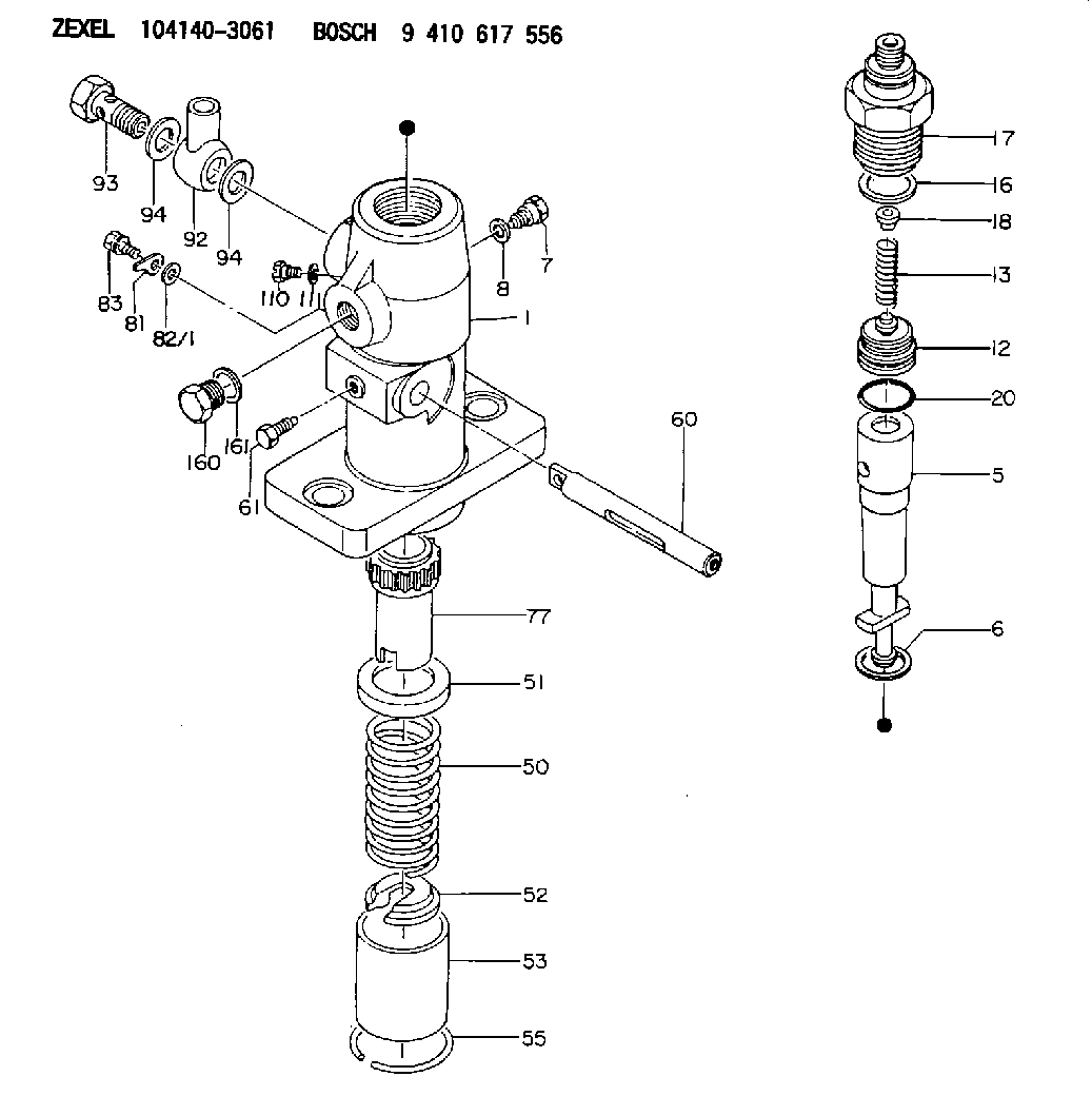
| 1. | [1] | 141052-7601 | PUMP HOUSING |
| 5. | [1] | 141175-0320 | PLUNGER-AND-BARREL ASSY |
| 6. | [1] | 029333-3010 | GASKET |
| 7. | [1] | 141133-3100 | CAPSULE |
| 8. | [1] | 029331-8010 | GASKET |
| 12. | [1] | 141110-5320 | DELIVERY-VALVE ASSEMBLY |
| 13. | [1] | 141112-0600 | COMPRESSION SPRING |
| 16. | [1] | 141115-6100 | GASKET |
| 17. | [1] | 141136-3800 | FITTING |
| 18. | [1] | 141117-3400 | SLOTTED WASHER |
| 20. | [1] | 029633-2040 | O-RING |
| 50. | [1] | 141215-0700 | COMPRESSION SPRING |
| 51. | [1] | 141216-2400 | SLOTTED WASHER |
| 52. | [1] | 141217-0300 | SLOTTED WASHER |
| 53. | [1] | 141218-4200 | GUIDE |
| 55. | [1] | 141220-0300 | LOCKING WASHER |
| 60. | [1] | 141223-9600 | CONTROL RACK |
| 61. | [1] | 141226-3000 | BLEEDER SCREW |
| 77. | [1] | 141241-0900 | CONTROL SLEEVE |
| 81. | [1] | 141245-2000 | POINTER |
| 82/1. | [0] | 023500-6210 | PLAIN WASHER D11&6.4T1.5 |
| 82/1. | [0] | 029300-6010 | PLAIN WASHER D11&6.4T0.8 |
| 82/1. | [0] | 029300-6020 | PLAIN WASHER D11&6.4T0.35 |
| 83. | [1] | 020006-1440 | BLEEDER SCREW M6P1L14 |
| 92. | [1] | 027118-1540 | INLET UNION |
| 93. | [1] | 029731-8200 | EYE BOLT |
| 94. | [2] | 141403-0400 | GASKET |
| 94. | [2] | 141403-0400 | GASKET |
| 110. | [1] | 140420-1600 | BLEEDER SCREW |
| 111. | [1] | 141421-0000 | GASKET |
| 160. | [1] | 029111-8090 | CAPSULE |
| 161. | [1] | 141403-0400 | GASKET |
Include in #2:
104140-3061
as INJECTION-PUMP ASSEMBLY
Cross reference number
Zexel num
Bosch num
Firm num
Name
104140-3061
C26640336192Z DAIHATSU
FUEL-INJECTION PUMP
K 24DA FUEL INJECTION PUMP PF-1C(D) PF
K 24DA FUEL INJECTION PUMP PF-1C(D) PF
Information:
MOVING WATER SLEEVES
1. 8S6692 Water Sleeve Tool.5. Disconnect oil cooler water outlet elbow at back side of timing gear cover.6. Remove bolts securing front support to frame.7. Raise the front of the engine 1 in. (25.4 mm) and block under the engine.
Never support the engine by placing blocking under the oil pan. Damage to the oil pan or suction bell will result.
8. Remove engine front support. Remove timing gear cover retaining bolts. These bolts vary in length. Mark each bolt and its location for correct installation.9. Install two 1P7406 Lifting Eye Bolts in timing gear cover. Attach a hoist and pry timing gear cover off dowels in cylinder block. Remove the timing gear cover, the weight is approx. 85 lbs. (40 kg).
REMOVING TIMING GEAR COVER
2. Timing gear cover.Install Timing Gear Cover
1. Clean all gasket surfaces on timing gear cover and cylinder block. Clean water sleeve bores in cylinder heads and inspect and lubricate O-rings before installing.2. Install timing gear cover gasket. Install water sleeves in timing gear cover before installing cover. Replacement water sleeves are color coded to insure that new sleeves have the correct sized orifice to control coolant flow in the different engines. The 1140, 1145, and 1150 Series [4.1 in. (104.1 mm) and 4.5 in. (114.3 mm) stroke] use a silver code. The 1160 [5.0 in. (127.0 mm) stroke] uses a gold code.3. Install two 1P7406 Lifting Eye Bolts in timing gear cover. Attach hoist and position cover on engine. Make sure the oil pump gear teeth and the crankshaft gear teeth mesh.4. Install the timing gear cover retaining bolts.5. Connect oil cooler water outlet elbow to back side of timing gear cover.6. Trim the timing gear cover gasket flush with bottom face of cylinder block. Gaskets not cut square and flush with oil pan face will leak.7. Use an 8S6692 Water Sleeve Tool to slide water sleeves into cylinder heads and install clamps.8. Install front support. Remove blocking from beneath engine and lower engine into position. Install and tighten front support-to-frame mounting bolts.9. Lubricate the lip of the crankshaft front seal with clean engine oil (SAE 30). Install the crankshaft pulley.10. Install oil pump suction bell, oil pan gasket and oil pan. Tighten oil pan retaining bolts to 17 3 lb. ft. (2.4 0.4 mkg).11. Connect water temperature sending unit. Install tachometer drive housing and connect tachometer drive cable.12. Install the power steering pump, vacuum pump, alternator, radiator and all other components that were removed or disconnected.13. Fill the cooling system and lubricating system to the correct levels.