Information fuel-injection pump
BOSCH
9 410 618 158
9410618158
ZEXEL
104140-3052
1041403052
NIIGATA-TEKKOU
W0C47000G
w0c47000g
Rating:
Components :
| 0. | INJECTION-PUMP ASSEMBLY | 104140-3052 |
| 1. | _ | |
| 2. | FUEL INJECTION PUMP | |
| 3. | NUMBER PLATE | |
| 4. | _ | |
| 5. | CAPSULE | |
| 6. | ADJUSTING DEVICE | |
| 7. | NOZZLE AND HOLDER ASSY | |
| 8. | Nozzle and Holder | |
| 9. | Open Pre:MPa(Kqf/cm2) | |
| 10. | NOZZLE-HOLDER | |
| 11. | NOZZLE |
Scheme ###:
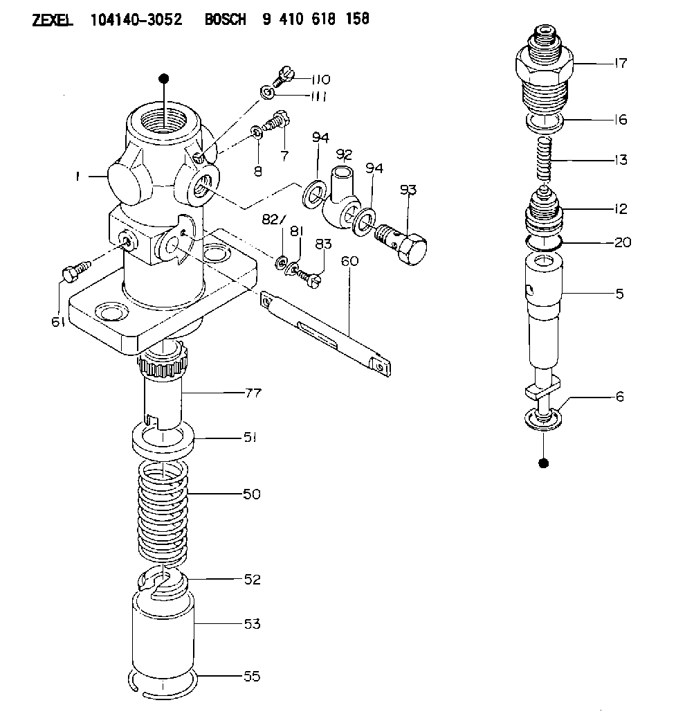
| 1. | [1] | 141053-0700 | PUMP HOUSING |
| 5. | [1] | 141170-0020 | PLUNGER-AND-BARREL ASSY C25 |
| 6. | [1] | 141162-0000 | GASKET |
| 7. | [1] | 141106-8000 | CAPSULE |
| 8. | [1] | 029330-8050 | GASKET |
| 12. | [1] | 141140-5120 | DELIVERY-VALVE ASSEMBLY C28 |
| 13. | [1] | 141112-2700 | COMPRESSION SPRING |
| 16. | [1] | 141115-4400 | GASKET |
| 17. | [1] | 141136-1620 | FITTING |
| 20. | [1] | 029633-2040 | O-RING |
| 50. | [1] | 141215-4900 | COMPRESSION SPRING |
| 51. | [1] | 141216-0500 | SLOTTED WASHER |
| 52. | [1] | 141217-0300 | SLOTTED WASHER |
| 53. | [1] | 141218-4200 | GUIDE |
| 55. | [1] | 141220-0300 | LOCKING WASHER |
| 60. | [1] | 141223-2100 | CONTROL RACK |
| 61. | [1] | 141226-3100 | BLEEDER SCREW |
| 77. | [1] | 141241-0900 | CONTROL SLEEVE |
| 81. | [1] | 141245-2000 | POINTER |
| 82/1. | [0] | 023500-6210 | PLAIN WASHER D11&6.4T1.5 |
| 82/1. | [0] | 029300-6010 | PLAIN WASHER D11&6.4T0.8 |
| 82/1. | [0] | 029300-6020 | PLAIN WASHER D11&6.4T0.35 |
| 83. | [1] | 020006-1440 | BLEEDER SCREW |
| 92. | [1] | 027118-1540 | INLET UNION |
| 93. | [1] | 029731-8200 | EYE BOLT |
| 94. | [2] | 026518-2240 | GASKET |
| 94. | [2] | 026518-2240 | GASKET |
| 110. | [1] | 140420-1800 | BLEEDER SCREW |
| 111. | [1] | 026506-1040 | GASKET |
Include in #2:
104140-3052
as INJECTION-PUMP ASSEMBLY
Cross reference number
Zexel num
Bosch num
Firm num
Name
Information:
WATER SLEEVE CLAMP
1. Clamp.3. Use water sleeve tool (2) to move water sleeve (3) into front cover.4. Remove the cylinder head retaining bolts (4) and (5).
MOVING WATER SLEEVE
2. 8S6692 Water Sleeve Tool. 3. Water sleeve.
CYLINDER HEAD
4. Bolts (four each head). 5. Bolts (eighteen each head).
Be sure fuel injection nozzles are removed before removing head. Nozzles extend through the head and nozzle tips can be broken off if nozzles are not removed from the head.
5. Install two 1P7407 Lifting Eye Bolts in the cylinder head. Attach a hoist and remove the cylinder head assembly, the weight is approx. 85 lbs. (39 kg).
REMOVING CYLINDER HEADInstall Cylinder Head Assemblies
1. Clean the mating surfaces of the cylinder head and cylinder block. Install new cylinder head gasket, clean and dry. Clean bores in cylinder head and inspect and lubricate O-rings for water sleeves.2. Install two 1P7407 Lifting Eye Bolts in the cylinder head. Attach a hoist and install the cylinder head assembly. Coat the cylinder head retaining bolt threads with 9M3710 Anti-Seize Compound. Install the bolts and tighten in the following Step sequence. Step A: Tighten bolts 1 through 18 in numerical order to 60 10 lb. ft. (8.3 1.4 mkg).Step B: Retighten bolts 1 through 18 in numerical order to 95 5 lb. ft. (13.1 0.7 mkg).Step C: Finally tighten bolts 1 through 18 in numerical order (hand tighten only) to 95 5 lb. ft. (13.1 0.7 mkg).Step D: Tighten bolts 19, 20, 21, and 22 in numerical order to 32 5 lb. ft. (4.4 0.7 mkg).
CYLINDER HEAD BOLT LOCATION3. Use the 8S6692 Water Sleeve Tool to slide water sleeve into cylinder head and install clamp.Disassemble Cylinder Head
1. Place head on the FT806 Cylinder Head Bench or the 8S6691 Cylinder Head Stand. Use FT967 Adapter Plates to mount head on the FT806 Cylinder Head Bench.2. Use a 5S1330 or 7F4291 Valve Spring Compressor (1) to remove the valves and valve springs.
REMOVING VALVES
1. 5S1330 Valve Spring Compressor illustrated.3. Use the 8S2263 Valve Spring Tester to check valve spring tension.4. The exhaust valve seats have replaceable inserts. To remove, use the 8S7170 Valve Seat Insert Puller Group.
REMOVING EXHAUST VALVE SEAT INSERTS The valve guides are cast in the cylinder head. If the guides show wear or bellmouthing, they can be restored to original tolerances through knurling.Assemble Cylinder Head
1. Lubricate valve stems with clean engine oil (SAE 30) before installing valves into cylinder head. Earlier engines use a valve spring retainer and washer combination instead of the one piece valve spring retainer shown.
CYLINDER HEAD