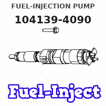
Information fuel-injection pump
BOSCH
9 410 617 942
9410617942
ZEXEL
104139-4090
1041394090
KUBOTA
1G91151012
1g91151012
Rating:
Compare Prices: .
As an associate, we earn commssions on qualifying purchases through the links below

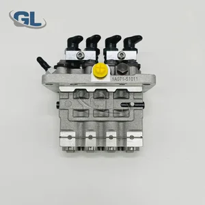
Fuel Injection Pump 1G911-51012 1G911-51011 1G911-51010 1G911-51013 for Kubota Engine V2203 V2203-D V2403
100% Apollo part number:1G911-51012 1G911-51011 || application: for Kubota Engine V2203 V2203-D V2403
100% Apollo part number:1G911-51012 1G911-51011 || application: for Kubota Engine V2203 V2203-D V2403

Fuel Injection Pump 1G911-51012 1G911-51011 1G911-51010 1G911-51013 for Kubota Engine V2203 V2203-D V2403
DIGERTECH Part number:1G911-51012 || Application: for Kubota Engine V2203 V2203-D V2403
DIGERTECH Part number:1G911-51012 || Application: for Kubota Engine V2203 V2203-D V2403

Fuel Injection Pump 1G911-51012 1G911-51011 1G911-51010 1G911-51013 for Kubota Engine V2203 V2203-D V2403
FGNTWP Part Number:1G911-51012, 104139-4090, 9410617942, 1G91151012, 1041394090, 1G911-5101-2, 9 410 617 942, F 01G 09Y 032, F01G09Y032, 104139-4091, 1041394091, 1G91151013, 1G911-51013, 1G911-5101-3, 9 410 617 885, 9410617885, 104139-4070, 1041394070, 1G91151011, 1G911-51011, 1G911-5101-1, 1G911-51010, 1G91151010, 1G911-5101-0 || Applications:for Kubota Engine V2203 V2203-D V2403
FGNTWP Part Number:1G911-51012, 104139-4090, 9410617942, 1G91151012, 1041394090, 1G911-5101-2, 9 410 617 942, F 01G 09Y 032, F01G09Y032, 104139-4091, 1041394091, 1G91151013, 1G911-51013, 1G911-5101-3, 9 410 617 885, 9410617885, 104139-4070, 1041394070, 1G91151011, 1G911-51011, 1G911-5101-1, 1G911-51010, 1G91151010, 1G911-5101-0 || Applications:for Kubota Engine V2203 V2203-D V2403
You can express buy:
USD 418.2
20-05-2025
20-05-2025
China Made New Fuel Injection Pump 1G911-51012 104139-4090 9410617942 compatible for Kubota V2403
Components :
| 0. | INJECTION-PUMP ASSEMBLY | 104139-4090 |
| 1. | _ | |
| 2. | FUEL INJECTION PUMP | |
| 3. | NUMBER PLATE | |
| 4. | _ | |
| 5. | CAPSULE | |
| 6. | ADJUSTING DEVICE | |
| 7. | NOZZLE AND HOLDER ASSY | 105118-7633 |
| 8. | Nozzle and Holder | 1G911-53002 |
| 9. | Open Pre:MPa(Kqf/cm2) | 18.6{190}/22.6{230} |
| 10. | NOZZLE-HOLDER | 105048-2221 |
| 11. | NOZZLE | 105019-1370 |
Scheme ###:
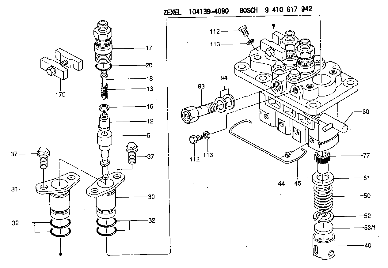
| 5. | [4] | 140163-1620 | PLUNGER-AND-BARREL ASSY |
| 12. | [4] | 140110-5520 | DELIVERY-VALVE ASSEMBLY |
| 13. | [4] | 140112-1700 | COMPRESSION SPRING |
| 16. | [4] | 140115-1400 | GASKET |
| 17. | [4] | 140116-8420 | FITTING |
| 18. | [4] | 140117-1700 | FILLER PIECE |
| 20. | [4] | 140118-0301 | O-RING |
| 30. | [3] | 140131-0521 | FLANGE BUSHING |
| 31. | [1] | 140131-1021 | FLANGE BUSHING |
| 32. | [8] | 140118-0201 | O-RING |
| 32. | [8] | 140118-0201 | O-RING |
| 37. | [8] | 140124-0200 | BLEEDER SCREW |
| 37. | [8] | 140124-0200 | BLEEDER SCREW |
| 40. | [4] | 140200-1620 | TAPPET |
| 44. | [4] | 140212-0300 | BEARING PIN |
| 45. | [1] | 140213-1500 | LOCKING WASHER |
| 50. | [4] | 140215-1900 | COMPRESSION SPRING |
| 51. | [4] | 140216-0800 | SLOTTED WASHER |
| 52. | [4] | 140217-2200 | SLOTTED WASHER |
| 53/1. | [1] | 140217-5000 | PLATE D19T2.60 |
| 53/1. | [1] | 140217-5100 | PLATE D19T2.65 |
| 53/1. | [1] | 140217-5200 | PLATE D19T2.70 |
| 53/1. | [1] | 140217-5300 | PLATE D19T2.75 |
| 53/1. | [1] | 140217-5400 | PLATE D19T2.80 |
| 53/1. | [1] | 140217-5500 | PLATE D19T2.85 |
| 53/1. | [1] | 140217-5600 | PLATE D19T2.90 |
| 53/1. | [1] | 140217-5700 | PLATE D19T2.95 |
| 53/1. | [1] | 140217-5800 | PLATE D19T3.00 |
| 53/1. | [1] | 140217-5900 | PLATE D19T3.05 |
| 53/1. | [1] | 140217-6000 | PLATE D19T3.10 |
| 53/1. | [1] | 140217-6100 | PLATE D19T3.15 |
| 53/1. | [1] | 140217-6200 | PLATE D19T3.20 |
| 53/1. | [1] | 140217-6300 | PLATE D19T3.25 |
| 53/1. | [1] | 140217-6400 | PLATE D19T3.30 |
| 53/1. | [1] | 140217-6500 | PLATE D19T3.35 |
| 53/1. | [1] | 140217-6600 | PLATE D19T3.40 |
| 53/1. | [1] | 140217-6700 | PLATE D19T3.45 |
| 53/1. | [1] | 140217-6800 | PLATE D19T3.50 |
| 53/1. | [1] | 140217-6900 | PLATE D19T3.55 |
| 53/1. | [1] | 140217-7000 | PLATE D19T3.60 |
| 53/1. | [1] | 140217-7100 | PLATE D19T3.65 |
| 53/1. | [1] | 140217-7200 | PLATE D19T3.70 |
| 53/1. | [1] | 140217-7300 | PLATE D19T3.75 |
| 53/1. | [1] | 140217-7400 | PLATE D19T3.80 |
| 53/1. | [1] | 140217-7500 | PLATE D19T3.85 |
| 53/1. | [1] | 140217-7600 | PLATE D19T3.90 |
| 53/1. | [1] | 140217-7700 | PLATE D19T3.95 |
| 53/1. | [1] | 140217-7800 | PLATE D19T4.00 |
| 53/1. | [1] | 140217-7900 | PLATE D19T4.05 |
| 53/1. | [1] | 140217-8000 | PLATE D19T4.10 |
| 53/1. | [1] | 140253-2000 | PLATE |
| 53/1. | [1] | 140253-2100 | PLATE |
| 53/1. | [1] | 140253-2200 | PLATE |
| 53/1. | [1] | 140253-2300 | PLATE |
| 53/1. | [1] | 140253-2400 | PLATE |
| 53/1. | [1] | 140253-2500 | PLATE |
| 53/1. | [1] | 140253-2600 | PLATE |
| 53/1. | [1] | 140253-2700 | PLATE |
| 53/1. | [1] | 140253-2800 | PLATE |
| 53/1. | [1] | 140253-2900 | PLATE |
| 53/1. | [1] | 140253-3000 | PLATE |
| 53/1. | [1] | 140253-3100 | PLATE |
| 53/1. | [1] | 140253-3200 | PLATE |
| 53/1. | [1] | 140253-3300 | PLATE |
| 53/1. | [1] | 140253-3400 | PLATE |
| 53/1. | [1] | 140253-3500 | PLATE |
| 53/1. | [1] | 140253-3600 | PLATE |
| 53/1. | [1] | 140253-3700 | PLATE |
| 53/1. | [1] | 140253-3800 | PLATE |
| 53/1. | [1] | 140253-3900 | PLATE |
| 53/1. | [1] | 140253-4000 | PLATE |
| 53/1. | [1] | 140253-4100 | PLATE |
| 53/1. | [1] | 140253-4200 | PLATE |
| 53/1. | [1] | 140253-4300 | PLATE |
| 53/1. | [1] | 140253-4400 | PLATE |
| 53/1. | [1] | 140253-4500 | PLATE |
| 53/1. | [1] | 140253-4600 | PLATE |
| 53/1. | [1] | 140253-4700 | PLATE |
| 53/1. | [1] | 140253-4800 | PLATE |
| 53/1. | [1] | 140253-4900 | PLATE |
| 60. | [1] | 140243-5720 | CONTROL RACK |
| 77. | [4] | 140241-4200 | CONTROL SLEEVE |
| 93. | [1] | 140402-2500 | EYE BOLT |
| 94. | [2] | 026512-1540 | GASKET D15.4&12.2T1.50 |
| 112. | [2] | 140420-1400 | BLEEDER SCREW |
| 112. | [2] | 140420-1400 | BLEEDER SCREW |
| 113. | [2] | 026508-1240 | GASKET D11.9&8.2T1 |
| 113. | [2] | 026508-1240 | GASKET D11.9&8.2T1 |
| 170. | [2] | 140445-0320 | PLATE |
Include in #1:
108622-2130
as _
Include in #2:
104139-4090
as INJECTION-PUMP ASSEMBLY
Cross reference number
Zexel num
Bosch num
Firm num
Name
1G91151012 KUBOTA
FUEL-INJECTION PUMP
* K 23AD FUEL INJECTION PUMP PFR-4KX PFR
* K 23AD FUEL INJECTION PUMP PFR-4KX PFR
Information:
Fuel system components identified are: 1-Fuel injection nozzles. 2-Fuel lines. 3-Fuel priming pump. 4-Governor. 5-Fuel injection pump housing. 6-Fuel filter. 7-Fuel transfer pump. 8-Tachometer drive.Governor
Removal and Installation
Refer to SERVICE GUIDE for Preliminary Information.
1-Cover. 2-Plate. 3-Cover assembly.
4-Collar. 5-Housing assembly.
6-Spring. 7-Weight assembly.Governor Disassembly and Assembly
1 Guide must be damaged to be removed. When installing a new guide, form the end of the guide against and all the way around the chamfer in the governor housing.2 When assembling weights to carrier, stake four places around each dowel on both ends. Each weight must have .001-.007 in. (0,03-0,18 mm) end play and pivot freely on its dowel.Fuel Transfer Pump
Refer to SERVICE GUIDE for Preliminary Information.8S6747 Sealing Compound 1,3 Apply a thin film of 8S6747 Sealing Compound to mating surfaces when assembling. Do not allow compound to enter pump.2 Use suitable puller and step plate to remove gear. Refer to GENERAL INSTRUCTIONS. Lubricate gear teeth with multipurpose grease before assembling pump to engine.Tachometer Drive
Fuel Pump Housing
Refer to SERVICE GUIDE for Preliminary Information. 8S2315 Wrench8S2244 Extractor.1, 2, 5 Inspect seals.3 Tighten nozzle finger tight on body.4 Use 8S2315 Wrench to remove.6 Use 8S2244 Extractor to remove and install fuel pumps. When installing, sight down the pump and align the notches in the bonnet and barrel with the mark 180° from the pump gear segment center tooth. Position the pump so the notches align with the guide pins in the housing bore. Align the pump gear segment center tooth with the fuel rack center notch. Install the pump. Keep a downward force on the pump and install bushing (4) until flush with the top of the housing. If the bushing can not be assembled this far by hand, remove it. Realign the components and install again.7 When removing retaining ring, do not damage or lose the check valve or spring retained in the bonnet.8, 9 Use extreme care when inserting plunger into barrel. Barrels and plungers are matched and are not interchangeable.10 Fuel rack must be removed before removing lifters and installed after installing lifters.10, 11 Install each spacer and lifter assembly in the same location from which they were removed. Keep them together and identified as to location.12, 13 Remove bearings (12) and (13) with a suitable driver. When installing, position bearing (12) with oil passages aligned vertically (that is, one at the top and one at the bottom). Install bearing (12) .195" .005" deep from the housing face.14, 15, 16 Use commercially available camshaft bearing removal tools. Align oil hole in bearing (14) with the oil passage in the housing.Fuel Ratio Control
Fuel Priming Pump