Information fuel-injection pump
BOSCH
9 410 617 936
9410617936
ZEXEL
104139-4080
1041394080
KUBOTA
1G79051011
1g79051011
Rating:
Compare Prices: .
As an associate, we earn commssions on qualifying purchases through the links below

WZCNLXLX Fuel Injection Pump 1G790-51011 104139-4080 9410617936 For Kubota V2403 Engine
WZCNLXLX Item Name:Fuel Injection Pump || Item Number:1G790-51011 104139-4080 9410617936 1G79051011 1041394080 || Application:For Kubota V2403 Engine || Note: If you are unsure if the product is suitable.In order not to delay your use of the parts, please provide your engine nameplate or serial number and part number, and we will help you confirm if it is suitable. To avoid unnecessary returns, please check the product image and part number to ensure it is the product you want. || Tip: Please contact us - we are a professional sales team and we have many products to offer to you. Many buyers are very satisfied with our service. You can get first-class products and high-quality services from us, believe me, you will have a pleasant shopping experience here.
WZCNLXLX Item Name:Fuel Injection Pump || Item Number:1G790-51011 104139-4080 9410617936 1G79051011 1041394080 || Application:For Kubota V2403 Engine || Note: If you are unsure if the product is suitable.In order not to delay your use of the parts, please provide your engine nameplate or serial number and part number, and we will help you confirm if it is suitable. To avoid unnecessary returns, please check the product image and part number to ensure it is the product you want. || Tip: Please contact us - we are a professional sales team and we have many products to offer to you. Many buyers are very satisfied with our service. You can get first-class products and high-quality services from us, believe me, you will have a pleasant shopping experience here.

$747.68
07 Dec 2024
CN: GSHLGAO Flagship sto
New Fuel Injection Pump Fits for Kubota Engine V2403-MDI Bobcat Excavator 430 1G790-51011 104139-4080 9410617936
GSHLGAO Part Name: Fuel Injection Pump || Part Number:1G79051011 1041394080 1G790-51011 104139-4080 9410617936 || Application: Designed to be compatible with the Kubota V2403-MDI engine commonly found in Bobcat equipment. || Notification-The application information provided is for guidance purposes only. It is recommended to verify the part number and conduct a comparison with the old parts before making a purchase. Should you have any inquiries, please do not hesitate to contact us. || Premium Selection-This item boasts consistent performance, exceptional reliability, effortless installation, and rapid response times.
GSHLGAO Part Name: Fuel Injection Pump || Part Number:1G79051011 1041394080 1G790-51011 104139-4080 9410617936 || Application: Designed to be compatible with the Kubota V2403-MDI engine commonly found in Bobcat equipment. || Notification-The application information provided is for guidance purposes only. It is recommended to verify the part number and conduct a comparison with the old parts before making a purchase. Should you have any inquiries, please do not hesitate to contact us. || Premium Selection-This item boasts consistent performance, exceptional reliability, effortless installation, and rapid response times.
Components :
| 0. | INJECTION-PUMP ASSEMBLY | 104139-4080 |
| 1. | _ | |
| 2. | FUEL INJECTION PUMP | |
| 3. | NUMBER PLATE | |
| 4. | _ | |
| 5. | CAPSULE | |
| 6. | ADJUSTING DEVICE | |
| 7. | NOZZLE AND HOLDER ASSY | 105118-8011 |
| 8. | Nozzle and Holder | 1G790-53002 |
| 9. | Open Pre:MPa(Kqf/cm2) | 18.6{190}/22.5{230} |
| 10. | NOZZLE-HOLDER | 105048-2221 |
| 11. | NOZZLE | 105019-1380 |
Scheme ###:
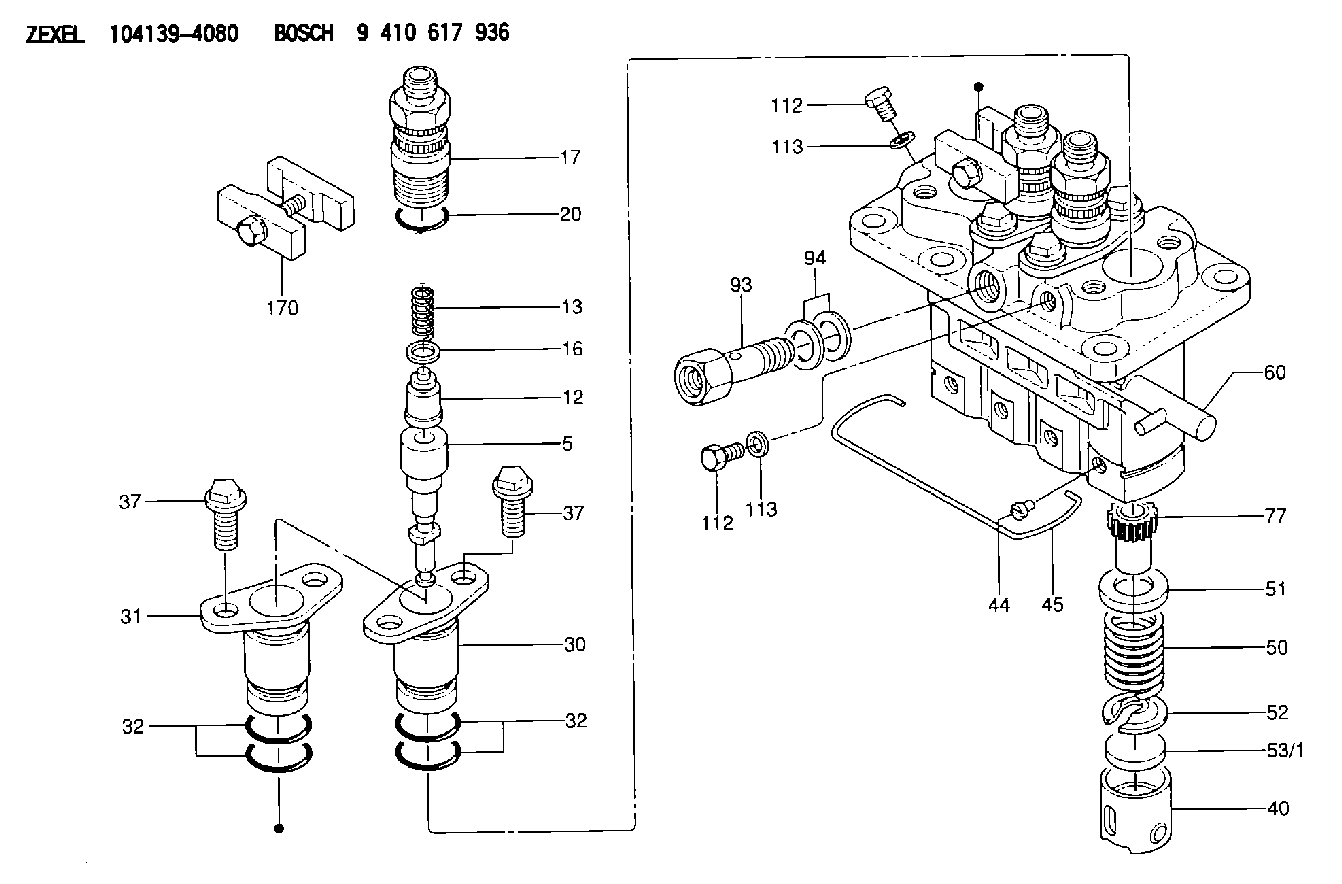
| 5. | [4] | 140163-2120 | PLUNGER-AND-BARREL ASSY |
| 12. | [4] | 140110-6120 | DELIVERY-VALVE ASSEMBLY |
| 13. | [4] | 140112-3400 | COMPRESSION SPRING |
| 16. | [4] | 140115-1400 | GASKET |
| 17. | [4] | 140116-8520 | FITTING |
| 20. | [4] | 140118-0301 | O-RING |
| 30. | [3] | 140131-0521 | FLANGE BUSHING |
| 31. | [1] | 140131-1021 | FLANGE BUSHING |
| 32. | [8] | 140118-0201 | O-RING |
| 32. | [8] | 140118-0201 | O-RING |
| 37. | [8] | 140124-0200 | BLEEDER SCREW |
| 37. | [8] | 140124-0200 | BLEEDER SCREW |
| 40. | [4] | 140200-1620 | TAPPET |
| 44. | [4] | 140212-0300 | BEARING PIN |
| 45. | [1] | 140213-1500 | LOCKING WASHER |
| 50. | [4] | 140215-1900 | COMPRESSION SPRING |
| 51. | [4] | 140216-0800 | SLOTTED WASHER |
| 52. | [4] | 140217-2200 | SLOTTED WASHER |
| 53/1. | [1] | 140217-5000 | PLATE D19T2.60 |
| 53/1. | [1] | 140217-5100 | PLATE D19T2.65 |
| 53/1. | [1] | 140217-5200 | PLATE D19T2.70 |
| 53/1. | [1] | 140217-5300 | PLATE D19T2.75 |
| 53/1. | [1] | 140217-5400 | PLATE D19T2.80 |
| 53/1. | [1] | 140217-5500 | PLATE D19T2.85 |
| 53/1. | [1] | 140217-5600 | PLATE D19T2.90 |
| 53/1. | [1] | 140217-5700 | PLATE D19T2.95 |
| 53/1. | [1] | 140217-5800 | PLATE D19T3.00 |
| 53/1. | [1] | 140217-5900 | PLATE D19T3.05 |
| 53/1. | [1] | 140217-6000 | PLATE D19T3.10 |
| 53/1. | [1] | 140217-6100 | PLATE D19T3.15 |
| 53/1. | [1] | 140217-6200 | PLATE D19T3.20 |
| 53/1. | [1] | 140217-6300 | PLATE D19T3.25 |
| 53/1. | [1] | 140217-6400 | PLATE D19T3.30 |
| 53/1. | [1] | 140217-6500 | PLATE D19T3.35 |
| 53/1. | [1] | 140217-6600 | PLATE D19T3.40 |
| 53/1. | [1] | 140217-6700 | PLATE D19T3.45 |
| 53/1. | [1] | 140217-6800 | PLATE D19T3.50 |
| 53/1. | [1] | 140217-6900 | PLATE D19T3.55 |
| 53/1. | [1] | 140217-7000 | PLATE D19T3.60 |
| 53/1. | [1] | 140217-7100 | PLATE D19T3.65 |
| 53/1. | [1] | 140217-7200 | PLATE D19T3.70 |
| 53/1. | [1] | 140217-7300 | PLATE D19T3.75 |
| 53/1. | [1] | 140217-7400 | PLATE D19T3.80 |
| 53/1. | [1] | 140217-7500 | PLATE D19T3.85 |
| 53/1. | [1] | 140217-7600 | PLATE D19T3.90 |
| 53/1. | [1] | 140217-7700 | PLATE D19T3.95 |
| 53/1. | [1] | 140217-7800 | PLATE D19T4.00 |
| 53/1. | [1] | 140217-7900 | PLATE D19T4.05 |
| 53/1. | [1] | 140217-8000 | PLATE D19T4.10 |
| 53/1. | [1] | 140253-2000 | PLATE |
| 53/1. | [1] | 140253-2100 | PLATE |
| 53/1. | [1] | 140253-2200 | PLATE |
| 53/1. | [1] | 140253-2300 | PLATE |
| 53/1. | [1] | 140253-2400 | PLATE |
| 53/1. | [1] | 140253-2500 | PLATE |
| 53/1. | [1] | 140253-2600 | PLATE |
| 53/1. | [1] | 140253-2700 | PLATE |
| 53/1. | [1] | 140253-2800 | PLATE |
| 53/1. | [1] | 140253-2900 | PLATE |
| 53/1. | [1] | 140253-3000 | PLATE |
| 53/1. | [1] | 140253-3100 | PLATE |
| 53/1. | [1] | 140253-3200 | PLATE |
| 53/1. | [1] | 140253-3300 | PLATE |
| 53/1. | [1] | 140253-3400 | PLATE |
| 53/1. | [1] | 140253-3500 | PLATE |
| 53/1. | [1] | 140253-3600 | PLATE |
| 53/1. | [1] | 140253-3700 | PLATE |
| 53/1. | [1] | 140253-3800 | PLATE |
| 53/1. | [1] | 140253-3900 | PLATE |
| 53/1. | [1] | 140253-4000 | PLATE |
| 53/1. | [1] | 140253-4100 | PLATE |
| 53/1. | [1] | 140253-4200 | PLATE |
| 53/1. | [1] | 140253-4300 | PLATE |
| 53/1. | [1] | 140253-4400 | PLATE |
| 53/1. | [1] | 140253-4500 | PLATE |
| 53/1. | [1] | 140253-4600 | PLATE |
| 53/1. | [1] | 140253-4700 | PLATE |
| 53/1. | [1] | 140253-4800 | PLATE |
| 53/1. | [1] | 140253-4900 | PLATE |
| 60. | [1] | 140243-5720 | CONTROL RACK |
| 77. | [4] | 140241-4200 | CONTROL SLEEVE |
| 93. | [1] | 140402-2500 | EYE BOLT |
| 94. | [2] | 026512-1540 | GASKET D15.4&12.2T1.50 |
| 112. | [2] | 140420-1400 | BLEEDER SCREW |
| 112. | [2] | 140420-1400 | BLEEDER SCREW |
| 113. | [2] | 026508-1240 | GASKET D11.9&8.2T1 |
| 113. | [2] | 026508-1240 | GASKET D11.9&8.2T1 |
| 170. | [2] | 140445-0320 | PLATE |
Include in #2:
104139-4080
as INJECTION-PUMP ASSEMBLY
Cross reference number
Zexel num
Bosch num
Firm num
Name
1G79051011 KUBOTA
FUEL-INJECTION PUMP
* K 23AD FUEL INJECTION PUMP PFR-4KX PFR
* K 23AD FUEL INJECTION PUMP PFR-4KX PFR
Information:
Cylinder Head Removal And Installation
Refer to SERVICE GUIDE for Preliminary Information.
1-Water pipe. 2-Fan and pulley mounting bracket assembly. 3-Water bypass line. 4-Air compressor water return line.
5-Turbocharger-to-inlet manifold air pipe. 6-Turbocharger lubrication oil supply line. 7-Turbocharger oil drain line. 8-Exhaust elbow. 9-Turbocharger. 10-Fuel lines (six). 11-Valve cover. 12-Cylinder head.Cylinder Head Disassembly And Assembly
Refer to SERVICE GUIDE for Preliminary Information.5F8353 Wrench5S1330 Valve Spring Compressor Group7S8858 Valve Guide Driver Bushing7S8859 Valve Guide DriverFT192 Driver9M3710 Anti-Seize Compound8S3080 Tool Group9S3084 Extractor Head9S3087 Extractor HeadApply 9M3710 Anti-Seize Compound to threads. Tighten all head bolts (1, 2 and 3) in Step sequence shown. Use gaskets (6) to position precombustion chambers (4) to prevent wiring interference. Install thinnest gasket (6) first. Install precombustion chamber and tighten to specified torque. If the glow plug opening is not positioned in the "go" range, remove the chamber and replace gasket with that called for in the diagram.4 Use 5F8353 Wrench to remove and install chamber. Coat threads with 9M3710 Anti-Seize Compound.5 Coat seal and mating surface in bore with liquid soap.7 Align opening in water director with "V" mark on head.8 Gasket to be clean and dry at installation.9, 10 Tool required: 5S1330 Valve Spring Compressor Group. Assemble spring with painted end up.11 Tool required to remove valve guide: 7S8859 Valve Guide Driver. Tools required to install valve guide: 7S8859 Valve Guide Driver, 7S8858 Valve Guide Driver Bushing.12 Valve seat inserts can be removed and new inserts installed in the cylinder heads. Tools required to remove inserts: 9S3080 Tool Group, 9S3084 Extractor Head, 9S3087 Extractor Head.13 Tool required to install bearing: FT192 Driver. Align hole in bearing with hole in rocker arm.