Information fuel-injection pump
BOSCH
F 01G 09Y 02S
f01g09y02s
ZEXEL
104139-3071
1041393071
KUBOTA
1G83051012
1g83051012
Rating:
Compare Prices: .
As an associate, we earn commssions on qualifying purchases through the links below

Fuel Injection Pump Compatible For Kubota D850 Engine 1G830-51011 104139-3070 F01G09Y02S Excavator Engine Replacement Parts
SDETASOQ Precise control: precise fuel injection, optimized combustion efficiency, reduced fuel consumption, and improved engine power output || Long lifespan and low maintenance: using high-strength wear-resistant alloy materials and corrosion-resistant coatings to reduce maintenance costs and downtime || Stable operation under all operating conditions: tested in extreme environments, continuously stable, and adaptable to various complex road and climate conditions || Silent and efficient operation: Adopting a noise reduction structure, it can maintain quietness even during high-speed operation, without interfering with the driving experience || Original New Fuel Injection Pump Compatible For Kubota D850 Engine 1G830-51011 104139-3070 F01G09Y02S Excavator Engine Replacement Parts
SDETASOQ Precise control: precise fuel injection, optimized combustion efficiency, reduced fuel consumption, and improved engine power output || Long lifespan and low maintenance: using high-strength wear-resistant alloy materials and corrosion-resistant coatings to reduce maintenance costs and downtime || Stable operation under all operating conditions: tested in extreme environments, continuously stable, and adaptable to various complex road and climate conditions || Silent and efficient operation: Adopting a noise reduction structure, it can maintain quietness even during high-speed operation, without interfering with the driving experience || Original New Fuel Injection Pump Compatible For Kubota D850 Engine 1G830-51011 104139-3070 F01G09Y02S Excavator Engine Replacement Parts

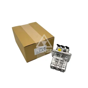
Fuel Injection Pump 1G830-51012 104139-3071 Compatible with Kubota D1803 Engine KX033-4 U35-4 L2501D L2501F L2501H
Generic 🔥Part Name:Fuel Injection Pump || 🔥Part Number:1G830-51012 104139-3071 || 🔥Application:Compatible with Kubota D1803 Engine KX033-4 U35-4 L2501D L2501F L2501H || 🔥Attention: If you are unsure if the product is suitable for your machine model. In order not to delay your use of the parts, please provide your engine nameplate or serial number and part number, and we will help you confirm if it is suitable. To avoid unnecessary returns, please carefully check the product image and part number to ensure that it is the product you want. Thank you for your support and understanding! || 🔥Tip: If you need any other parts, please contact us - we are a professional sales team and have many products to offer to you. Many buyers are very satisfied with our service. You can get first-class products and high-quality services from us, believe me, you will have a pleasant shopping experience here.
Generic 🔥Part Name:Fuel Injection Pump || 🔥Part Number:1G830-51012 104139-3071 || 🔥Application:Compatible with Kubota D1803 Engine KX033-4 U35-4 L2501D L2501F L2501H || 🔥Attention: If you are unsure if the product is suitable for your machine model. In order not to delay your use of the parts, please provide your engine nameplate or serial number and part number, and we will help you confirm if it is suitable. To avoid unnecessary returns, please carefully check the product image and part number to ensure that it is the product you want. Thank you for your support and understanding! || 🔥Tip: If you need any other parts, please contact us - we are a professional sales team and have many products to offer to you. Many buyers are very satisfied with our service. You can get first-class products and high-quality services from us, believe me, you will have a pleasant shopping experience here.

104139-3071 1G830-51012 Fuel Injection Pump Fits for Kubota Engine D1803 1041393071 1G83051012
Generic 🔥Part Name:Fuel Injection Pump || 🔥Part Number:104139-3071 1G830-51012 1041393071 1G83051012 || 🔥Application:Fits for Kubota Engine D1803 || 🔥Attention: If you are unsure if the product is suitable for your machine model. In order not to delay your use of the parts, please provide your engine nameplate or serial number and part number, and we will help you confirm if it is suitable. To avoid unnecessary returns, please carefully check the product image and part number to ensure that it is the product you want. Thank you for your support and understanding! || 🔥Tip: If you need any other parts, please contact us - we are a professional sales team and have many products to offer to you. Many buyers are very satisfied with our service. You can get first-class products and high-quality services from us, believe me, you will have a pleasant shopping experience here.
Generic 🔥Part Name:Fuel Injection Pump || 🔥Part Number:104139-3071 1G830-51012 1041393071 1G83051012 || 🔥Application:Fits for Kubota Engine D1803 || 🔥Attention: If you are unsure if the product is suitable for your machine model. In order not to delay your use of the parts, please provide your engine nameplate or serial number and part number, and we will help you confirm if it is suitable. To avoid unnecessary returns, please carefully check the product image and part number to ensure that it is the product you want. Thank you for your support and understanding! || 🔥Tip: If you need any other parts, please contact us - we are a professional sales team and have many products to offer to you. Many buyers are very satisfied with our service. You can get first-class products and high-quality services from us, believe me, you will have a pleasant shopping experience here.
You can express buy:
USD 792.25
14-06-2025
14-06-2025
Hot selling factory prices 1G830-51011 104139-3070 F01G09Y02S Compatible with Kubota D850 Engine
Cross reference number
Zexel num
Bosch num
Firm num
Name
Information:
start by:a) remove pistons1. Put covers on journals of crankshaft for protection from dirt or water. 2. Remove the cylinder liners with tool (A) as shown.Install Cylinder Liners
1. Clean the cylinder liners and the liner bores in the cylinder block. 2. Install cylinder liners (1) in the block without the O-ring seals or filler band.3. Check the cylinder liner projection as follows: a) Install the 3/4"-16 NF bolts, 3 in. long and the 2F126 Washers of tooling (A) on the cylinder block next to each liner. Tighten the bolts evenly, in four steps: 10 lb.ft. (14 N m), 25 lb.ft. (35 N m) 50 lb.ft. (70 N m) and then turn to 70 lb.ft. (95 N m).b) Put the adapter plate and one plate of tooling (A) on top of the liner and install the remainder of tooling (A). Be sure the bar is in position at the center of the liner. Tighten the bolts evenly, in four steps to a torque of: 5 lb.ft. (7 N m), 15 lb.ft. (20 N m), 25 lb.ft. (35 N m), then to 50 lb.ft. (70 N m).c) Check to be sure the distance from the bottom edge of the bar to the top of the cylinder block is the same on both sides of the liner. d) Check the cylinder liner projection with tooling (B) at four locations around the liner. SPECIAL INSTRUCTION (GMG00623) is included with the tool.e) Liner projection must be .001 to .006 in. (0.03 to 0.15 mm). Measurements on the same liner must not be different by more than .002 in. (0.05 mm). Average measurements between liners next to each other must not be different by more than .002 in. (0.05 mm).The maximum difference in the average projection for all cylinder liners under one cylinder head must ot be more than .004 in. (0.10 mm). If the liner is turned in the bore it can make a difference in the liner projection.f. If the liner projection is not .001 to .006 in. (0.03 to 0.15 mm), check the thickness of the following parts: spacer plate, spacer plate gasket, and cylinder liner flange (3). The thickness of the spacer plate must be .338 .001 in. (8.59 0.03 mm). The thickness of the spacer plate gasket must be .008 .001 in. (0.20 0.03 mm). The thickness of the cylinder liner flange must be .3500 .0008 in. (8.890 0.020 mm). The cylinder liner projection can be changed by the correction of the counterbore in the block to a minimum depth of .030 in. (0.76 mm) with a cylinder block counterboring tool. See SPECIAL INSTRUCTION, Form FM055228. Shims are available for the adjustment of the liner projection. 5. Put a mark on the liner and block so the liner can be installed in the same position from which it was removed.6. Remove tooling (a) and (B). Remove the liner. Install new O-ring seals on the liners. 7. Put liquid soap on the O-ring seals
1. Clean the cylinder liners and the liner bores in the cylinder block. 2. Install cylinder liners (1) in the block without the O-ring seals or filler band.3. Check the cylinder liner projection as follows: a) Install the 3/4"-16 NF bolts, 3 in. long and the 2F126 Washers of tooling (A) on the cylinder block next to each liner. Tighten the bolts evenly, in four steps: 10 lb.ft. (14 N m), 25 lb.ft. (35 N m) 50 lb.ft. (70 N m) and then turn to 70 lb.ft. (95 N m).b) Put the adapter plate and one plate of tooling (A) on top of the liner and install the remainder of tooling (A). Be sure the bar is in position at the center of the liner. Tighten the bolts evenly, in four steps to a torque of: 5 lb.ft. (7 N m), 15 lb.ft. (20 N m), 25 lb.ft. (35 N m), then to 50 lb.ft. (70 N m).c) Check to be sure the distance from the bottom edge of the bar to the top of the cylinder block is the same on both sides of the liner. d) Check the cylinder liner projection with tooling (B) at four locations around the liner. SPECIAL INSTRUCTION (GMG00623) is included with the tool.e) Liner projection must be .001 to .006 in. (0.03 to 0.15 mm). Measurements on the same liner must not be different by more than .002 in. (0.05 mm). Average measurements between liners next to each other must not be different by more than .002 in. (0.05 mm).The maximum difference in the average projection for all cylinder liners under one cylinder head must ot be more than .004 in. (0.10 mm). If the liner is turned in the bore it can make a difference in the liner projection.f. If the liner projection is not .001 to .006 in. (0.03 to 0.15 mm), check the thickness of the following parts: spacer plate, spacer plate gasket, and cylinder liner flange (3). The thickness of the spacer plate must be .338 .001 in. (8.59 0.03 mm). The thickness of the spacer plate gasket must be .008 .001 in. (0.20 0.03 mm). The thickness of the cylinder liner flange must be .3500 .0008 in. (8.890 0.020 mm). The cylinder liner projection can be changed by the correction of the counterbore in the block to a minimum depth of .030 in. (0.76 mm) with a cylinder block counterboring tool. See SPECIAL INSTRUCTION, Form FM055228. Shims are available for the adjustment of the liner projection. 5. Put a mark on the liner and block so the liner can be installed in the same position from which it was removed.6. Remove tooling (a) and (B). Remove the liner. Install new O-ring seals on the liners. 7. Put liquid soap on the O-ring seals