Information fuel-injection pump
BOSCH
F 01G 09Y 01R
f01g09y01r
ZEXEL
104139-3070
1041393070
KUBOTA
1G830-51011
1g83051011

Rating:
Compare Prices: .
As an associate, we earn commssions on qualifying purchases through the links below

Fuel Injection Pump Compatible For Kubota D850 Engine 1G830-51011 104139-3070 F01G09Y02S Excavator Engine Replacement Parts
SDETASOQ Precise control: precise fuel injection, optimized combustion efficiency, reduced fuel consumption, and improved engine power output || Long lifespan and low maintenance: using high-strength wear-resistant alloy materials and corrosion-resistant coatings to reduce maintenance costs and downtime || Stable operation under all operating conditions: tested in extreme environments, continuously stable, and adaptable to various complex road and climate conditions || Silent and efficient operation: Adopting a noise reduction structure, it can maintain quietness even during high-speed operation, without interfering with the driving experience || Original New Fuel Injection Pump Compatible For Kubota D850 Engine 1G830-51011 104139-3070 F01G09Y02S Excavator Engine Replacement Parts
SDETASOQ Precise control: precise fuel injection, optimized combustion efficiency, reduced fuel consumption, and improved engine power output || Long lifespan and low maintenance: using high-strength wear-resistant alloy materials and corrosion-resistant coatings to reduce maintenance costs and downtime || Stable operation under all operating conditions: tested in extreme environments, continuously stable, and adaptable to various complex road and climate conditions || Silent and efficient operation: Adopting a noise reduction structure, it can maintain quietness even during high-speed operation, without interfering with the driving experience || Original New Fuel Injection Pump Compatible For Kubota D850 Engine 1G830-51011 104139-3070 F01G09Y02S Excavator Engine Replacement Parts

Fuel Injection Pump 1G830-51012 1G830-51010 1G830-51011 for Kubota Engine D1703 D1803 D850 Excavator KX033-4 KX033-4CA U35-4 U35-4CA
FGNTWP Part Number:1G830-51012, 104139-3071, 1G83051012, 1041393071, 1G830-51011, 104139-3070, F01G09Y02S, F 01G 09Y 02S , 1G83051011, 1041393070, 1G830-5101-2, 1G830-5101-1, 1G830-51010, 1G830-51013, 1G83051010, 1G83051013, 1G830-5101-0, 1G830-5101-3, F 01G 09Y 01R, F01G09Y01R || Application:for Kubota Engine D1703 D1803 D850 Excavator KX033-4 KX033-4CA U35-4 U35-4CA
FGNTWP Part Number:1G830-51012, 104139-3071, 1G83051012, 1041393071, 1G830-51011, 104139-3070, F01G09Y02S, F 01G 09Y 02S , 1G83051011, 1041393070, 1G830-5101-2, 1G830-5101-1, 1G830-51010, 1G830-51013, 1G83051010, 1G83051013, 1G830-5101-0, 1G830-5101-3, F 01G 09Y 01R, F01G09Y01R || Application:for Kubota Engine D1703 D1803 D850 Excavator KX033-4 KX033-4CA U35-4 U35-4CA

Original Fuel Injection Pump Compatible With Kubota D850 Engine 1G830-51011 104139-3070 F01G09Y02S Excavator Engine Replacement Parts
YERCBX Enhance the engine's power output || Low-noise operation: Optimized internal structure and materials, resulting in low noise during operation || The key components have excellent wear resistance, extending the overall service life || Integrated design: Compact structure, small space occupation, and convenient for vehicle installation and layout. || Easy maintenance: The design is reasonable, and daily inspection and maintenance operations are simple, saving time
YERCBX Enhance the engine's power output || Low-noise operation: Optimized internal structure and materials, resulting in low noise during operation || The key components have excellent wear resistance, extending the overall service life || Integrated design: Compact structure, small space occupation, and convenient for vehicle installation and layout. || Easy maintenance: The design is reasonable, and daily inspection and maintenance operations are simple, saving time
You can express buy:
USD 792.25
14-06-2025
14-06-2025
Hot selling factory prices 1G830-51011 104139-3070 F01G09Y02S Compatible with Kubota D850 Engine
Components :
| 0. | INJECTION-PUMP ASSEMBLY | 104139-3070 |
| 1. | _ | |
| 2. | FUEL INJECTION PUMP | |
| 3. | NUMBER PLATE | |
| 4. | _ | |
| 5. | CAPSULE | |
| 6. | ADJUSTING DEVICE | |
| 7. | NOZZLE AND HOLDER ASSY | |
| 8. | Nozzle and Holder | |
| 9. | Open Pre:MPa(Kqf/cm2) | |
| 10. | NOZZLE-HOLDER | |
| 11. | NOZZLE |
Scheme ###:
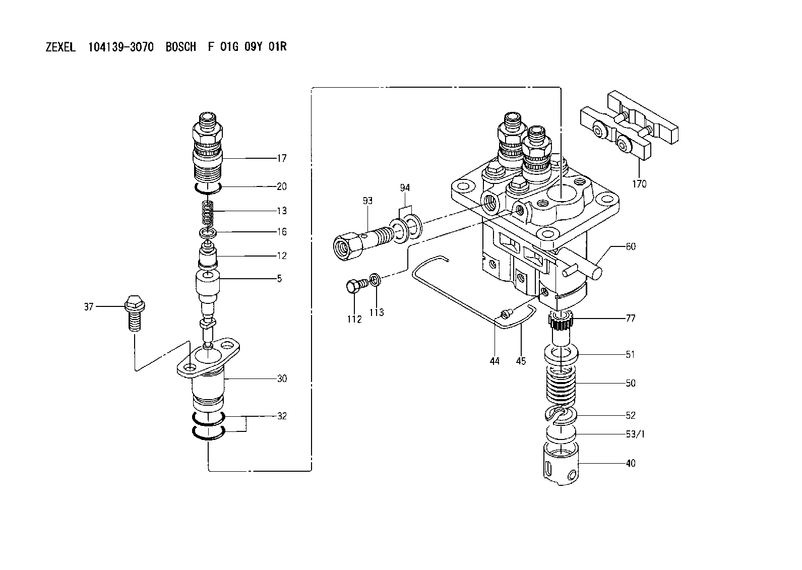
| 5. | [3] | 140163-5220 | PLUNGER-AND-BARREL ASSY K |
| 12. | [3] | 140110-6220 | DELIVERY-VALVE ASSEMBLY K49 |
| 13. | [3] | 140112-3400 | COMPRESSION SPRING |
| 16. | [3] | 140115-1400 | GASKET |
| 17. | [3] | 140116-8520 | FITTING |
| 20. | [3] | 140118-0301 | O-RING |
| 30. | [3] | 140131-1220 | FLANGE BUSHING |
| 32. | [6] | 140118-0201 | O-RING |
| 37. | [6] | 140124-0200 | BLEEDER SCREW |
| 40. | [3] | 140200-3020 | TAPPET |
| 44. | [3] | 140212-0300 | BEARING PIN |
| 45. | [1] | 140213-1400 | LOCKING WASHER |
| 50. | [3] | 140215-2300 | COMPRESSION SPRING |
| 51. | [3] | 140216-0800 | SLOTTED WASHER |
| 52. | [3] | 140217-2200 | SLOTTED WASHER |
| 53/1. | [1] | 140253-5001 | PLATE D19T2.60 |
| 53/1. | [1] | 140253-5101 | PLATE D19T2.65 |
| 53/1. | [1] | 140253-5201 | PLATE D19T2.70 |
| 53/1. | [1] | 140253-5301 | PLATE D19T2.75 |
| 53/1. | [1] | 140253-5401 | PLATE D19T2.80 |
| 53/1. | [1] | 140253-5501 | PLATE D19T2.85 |
| 53/1. | [1] | 140253-5601 | PLATE D19T2.90 |
| 53/1. | [1] | 140253-5701 | PLATE D19T2.95 |
| 53/1. | [1] | 140253-5801 | PLATE D19T3.00 |
| 53/1. | [1] | 140253-5901 | PLATE D19T3.05 |
| 53/1. | [1] | 140253-6001 | PLATE D19T3.10 |
| 53/1. | [1] | 140253-6101 | PLATE D19T3.15 |
| 53/1. | [1] | 140253-6201 | PLATE D19T3.20 |
| 53/1. | [1] | 140253-6301 | PLATE D19T3.25 |
| 53/1. | [1] | 140253-6401 | PLATE D19T3.30 |
| 53/1. | [1] | 140253-6501 | PLATE D19T3.35 |
| 53/1. | [1] | 140253-6601 | PLATE D19T3.40 |
| 53/1. | [1] | 140253-6701 | PLATE D19T3.45 |
| 53/1. | [1] | 140253-6801 | PLATE D19T3.50 |
| 53/1. | [1] | 140253-6901 | PLATE D19T3.55 |
| 53/1. | [1] | 140253-7001 | PLATE D19T3.60 |
| 53/1. | [1] | 140253-7101 | PLATE D19T3.65 |
| 53/1. | [1] | 140253-7201 | PLATE D19T3.70 |
| 53/1. | [1] | 140253-7301 | PLATE D19T3.75 |
| 53/1. | [1] | 140253-7401 | PLATE D19T3.80 |
| 53/1. | [1] | 140253-7501 | PLATE D19T3.85 |
| 53/1. | [1] | 140253-7601 | PLATE D19T3.90 |
| 53/1. | [1] | 140253-7701 | PLATE D19T3.95 |
| 53/1. | [1] | 140253-7801 | PLATE D19T4.00 |
| 53/1. | [1] | 140253-7901 | PLATE D19T4.05 |
| 53/1. | [1] | 140253-8001 | PLATE D19T4.10 |
| 53/1. | [1] | 140253-8101 | PLATE D19T4.15 |
| 53/1. | [1] | 140253-8201 | PLATE D19T4.20 |
| 53/1. | [1] | 140253-8301 | PLATE D19T4.25 |
| 53/1. | [1] | 140253-8401 | PLATE D19T4.30 |
| 53/1. | [1] | 140253-8501 | PLATE D19T4.35 |
| 53/1. | [1] | 140253-8601 | PLATE D19T4.40 |
| 53/1. | [1] | 140253-8701 | PLATE D19T4.45 |
| 53/1. | [1] | 140253-8801 | PLATE D19T4.50 |
| 53/1. | [1] | 140253-8901 | PLATE D19T4.55 |
| 53/1. | [1] | 140253-9001 | PLATE D19T4.60 |
| 53/1. | [1] | 140253-9101 | PLATE D19T4.65 |
| 53/1. | [1] | 140253-9201 | PLATE D19T4.70 |
| 53/1. | [1] | 140253-9301 | PLATE D19T4.75 |
| 53/1. | [1] | 140253-9401 | PLATE D19T4.80 |
| 53/1. | [1] | 140296-0000 | PLATE D19T2.625 |
| 53/1. | [1] | 140296-0100 | PLATE D19T2.675 |
| 53/1. | [1] | 140296-0200 | PLATE D19T2.725 |
| 53/1. | [1] | 140296-0300 | PLATE D19T2.775 |
| 53/1. | [1] | 140296-0400 | PLATE D19T2.825 |
| 53/1. | [1] | 140296-0500 | PLATE D19T2.875 |
| 53/1. | [1] | 140296-0600 | PLATE D19T2.925 |
| 53/1. | [1] | 140296-0700 | PLATE D19T2.975 |
| 53/1. | [1] | 140296-0800 | PLATE D19T3.025 |
| 53/1. | [1] | 140296-0900 | PLATE D19T3.075 |
| 53/1. | [1] | 140296-1000 | PLATE D19T3.125 |
| 53/1. | [1] | 140296-1100 | PLATE D19T3.175 |
| 53/1. | [1] | 140296-1200 | PLATE D19T3.225 |
| 53/1. | [1] | 140296-1300 | PLATE D19T3.275 |
| 53/1. | [1] | 140296-1400 | PLATE D19T3.325 |
| 53/1. | [1] | 140296-1500 | PLATE D19T3.375 |
| 53/1. | [1] | 140296-1600 | PLATE D19T3.425 |
| 53/1. | [1] | 140296-1700 | PLATE D19T3.475 |
| 53/1. | [1] | 140296-1800 | PLATE D19T3.525 |
| 53/1. | [1] | 140296-1900 | PLATE D19T3.575 |
| 53/1. | [1] | 140296-2000 | PLATE D19T3.625 |
| 53/1. | [1] | 140296-2100 | PLATE D19T3.675 |
| 53/1. | [1] | 140296-2200 | PLATE D19T3.725 |
| 53/1. | [1] | 140296-2300 | PLATE D19T3.775 |
| 53/1. | [1] | 140296-2400 | PLATE D19T3.825 |
| 53/1. | [1] | 140296-2500 | PLATE D19T3.875 |
| 53/1. | [1] | 140296-2600 | PLATE D19T3.925 |
| 53/1. | [1] | 140296-2700 | PLATE D19T3.975 |
| 53/1. | [1] | 140296-2800 | PLATE D19T4.025 |
| 53/1. | [1] | 140296-2900 | PLATE D19T4.075 |
| 53/1. | [1] | 140296-3000 | PLATE D19T4.125 |
| 53/1. | [1] | 140296-3100 | PLATE D19T4.175 |
| 53/1. | [1] | 140296-3200 | PLATE D19T4.225 |
| 53/1. | [1] | 140296-3300 | PLATE D19T4.275 |
| 53/1. | [1] | 140296-3400 | PLATE D19T4.325 |
| 53/1. | [1] | 140296-3500 | PLATE D19T4.375 |
| 53/1. | [1] | 140296-3600 | PLATE D19T4.425 |
| 53/1. | [1] | 140296-3700 | PLATE D19T4.475 |
| 53/1. | [1] | 140296-3800 | PLATE D19T4.525 |
| 53/1. | [1] | 140296-3900 | PLATE D19T4.575 |
| 53/1. | [1] | 140296-4000 | PLATE D19T4.625 |
| 53/1. | [1] | 140296-4100 | PLATE D19T4.675 |
| 53/1. | [1] | 140296-4200 | PLATE D19T4.725 |
| 53/1. | [1] | 140296-4300 | PLATE D19T4.775 |
| 60. | [1] | 140243-4420 | CONTROL RACK |
| 77. | [3] | 140241-4200 | CONTROL SLEEVE |
| 93. | [1] | 140402-2500 | EYE BOLT |
| 94. | [2] | 026512-1540 | GASKET |
| 112. | [1] | 140420-1400 | BLEEDER SCREW |
| 113. | [1] | 026508-1240 | GASKET D11.9&8.2T1.0 |
| 170. | [1] | 140445-0521 | PLATE |
Include in #2:
104139-3070
as INJECTION-PUMP ASSEMBLY
Cross reference number
Zexel num
Bosch num
Firm num
Name
Information:
3. Remove nuts (1) and the bearing caps. Push the rods and pistons up until the rings are out of the cylinder liners. 4. Remove pistons (2) and connecting rod from the cylinder liners.5. Do Steps 1 through 4 for the remainder of the pistons.Install Pistons
1. Put clean engine oil on piston rings, connecting rod bearings and cylinder liners.
Never install the ring compressor on the piston unless the cylinder liner is used as a guide. Damage to the piston rings can be the result.
2. Use tool (A) and install pistons (1) and connecting rods in the cylinder liner. Be sure the number on the tab groove side of the connecting rod is on the opposite side from the camshaft.3. Install the bearing caps on the connecting rods with number on side of the bearing caps on the same side and same number as on the connecting rod.4. Install the nuts and tighten to a torque of 60 6 lb.ft. (80 8 N m). Put a mark on the nuts and caps and tighten nuts an extra 120°.5. Do Steps 1 through 4 for the remainder of the pistons.end by:a) install oil pumpb) install cylinder headDisassemble And Assemble Pistons
start by:a) remove pistons 1. Remove bearings (2) from the connecting rod and connecting rod cap.2. Remove retainer ring (1). Remove piston pin (3) from the piston and connecting rod. 3. Use tool (A) to remove the piston rings (4) from the piston. 4. Heat the connecting rod to a temperature of 350 to 500°F (177 to 260°C). Put connecting rod (6) in position on the base plate of tooling (B). Put a new bearing (5) on the adapter of tooling (B). Put the adapter in position in the connecting rod and base plate of tooling (B). 5. Install the pusher adapter (8) and pusher (7) from tooling (B) on the adapter. The old bearing is pushed out by tooling (B) as the new bearing is installed.6. Use tooling (B) to push the new bearing (5) into the connecting rod (6) until the push adapter of tooling (B) makes full contact with the connecting rod surface. See USE OF PISTON PIN BEARING REMOVAL AND INSTALLATION TOOLS, SPECIAL INSTRUCTION, Form No. SMHS7295. Use tooling (C) for later type connecting rods (tapered ends).7. Check the piston pin bore diameter after the bearing is installed. The correct dimension is 2.0012 .0003 in. (50.830 0.008 mm).8. Clean the ring grooves in the piston before rings are installed. The two compression rings have marks "UP-1" and "UP-2". The rings must be installed with these marks toward the top of the piston with "UP-1" as the top ring. After installation of all three piston rings, put piston rings in position so gaps in rings are 120° apart. 9. Use tool (A) to install the piston rings on the piston. 10. Install bearings (2) in the connecting rod and connecting rod cap. Be sure the tabs in back of bearings are in the tab