Information fuel-injection pump
BOSCH
9 410 618 384
9410618384
ZEXEL
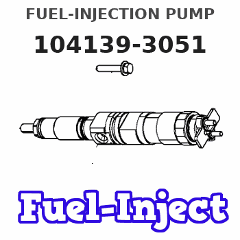
104139-3051
1041393051
KUBOTA
1G17051011
1g17051011
Rating:
Compare Prices: .
As an associate, we earn commssions on qualifying purchases through the links below

Original Fuel Injection Pump Compatible With Kubota D850 1G170-51011 104139-3051 9410618384 Excavator Engine Replacement Parts
YERCBX The key components have excellent wear resistance, extending the overall service life || Integrated design: Compact structure, small space occupation, and convenient for vehicle installation and layout. || Easy maintenance: The design is reasonable, and daily inspection and maintenance operations are simple, saving time || Lightweight design: Reducing its own weight helps to achieve overall lightweighting of the vehicle || The installation interface design is convenient for installation and saves installation time.
YERCBX The key components have excellent wear resistance, extending the overall service life || Integrated design: Compact structure, small space occupation, and convenient for vehicle installation and layout. || Easy maintenance: The design is reasonable, and daily inspection and maintenance operations are simple, saving time || Lightweight design: Reducing its own weight helps to achieve overall lightweighting of the vehicle || The installation interface design is convenient for installation and saves installation time.

New Fuel Injection Pump Compatible For Kubota D850 1G170-51011 104139-3051 9410618384 Excavator Engine Replacement Parts
TBEFQVAW Lightweight design: effectively reduces vehicle load, improves fuel economy, and facilitates installation and handling || Multi specification adaptation: providing multiple flow specifications and models to meet the needs of different displacement engines || Adaptive installation: Standardized interface design, compatible with 95% of mainstream engine models, no need for complex modifications || Anti corrosion coating: The surface of key components is covered with anti-corrosion coating, which is not afraid of humid coastal environments and harsh weather conditions || New Fuel Injection Pump Compatible For Kubota D850 1G170-51011 104139-3051 9410618384 Excavator Engine Replacement Parts
TBEFQVAW Lightweight design: effectively reduces vehicle load, improves fuel economy, and facilitates installation and handling || Multi specification adaptation: providing multiple flow specifications and models to meet the needs of different displacement engines || Adaptive installation: Standardized interface design, compatible with 95% of mainstream engine models, no need for complex modifications || Anti corrosion coating: The surface of key components is covered with anti-corrosion coating, which is not afraid of humid coastal environments and harsh weather conditions || New Fuel Injection Pump Compatible For Kubota D850 1G170-51011 104139-3051 9410618384 Excavator Engine Replacement Parts
Components :
| 0. | INJECTION-PUMP ASSEMBLY | 104139-3051 |
| 1. | _ | |
| 2. | FUEL INJECTION PUMP | |
| 3. | NUMBER PLATE | |
| 4. | _ | |
| 5. | CAPSULE | |
| 6. | ADJUSTING DEVICE | |
| 7. | NOZZLE AND HOLDER ASSY | 105118-8192 |
| 8. | Nozzle and Holder | |
| 9. | Open Pre:MPa(Kqf/cm2) | 18.6{190}/22.6{230} |
| 10. | NOZZLE-HOLDER | 105048-2222 |
| 11. | NOZZLE | 105017-3020 |
Scheme ###:
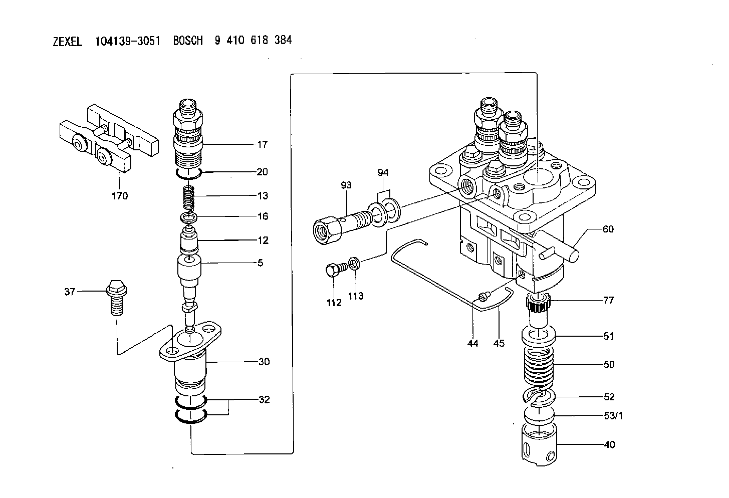
| 5. | [3] | 140163-3420 | PLUNGER-AND-BARREL ASSY |
| 12. | [3] | 140110-6220 | DELIVERY-VALVE ASSEMBLY |
| 13. | [3] | 140112-3400 | COMPRESSION SPRING |
| 16. | [3] | 140115-1400 | GASKET |
| 17. | [3] | 140116-8520 | FITTING |
| 20. | [3] | 140118-0301 | O-RING |
| 30. | [3] | 140131-0521 | FLANGE BUSHING |
| 32. | [6] | 140118-0201 | O-RING |
| 37. | [6] | 140124-0200 | BLEEDER SCREW |
| 40. | [3] | 140200-3120 | TAPPET |
| 44. | [3] | 140212-0300 | BEARING PIN |
| 45. | [1] | 140213-1400 | LOCKING WASHER |
| 50. | [3] | 140215-1900 | COMPRESSION SPRING |
| 51. | [3] | 140216-0800 | SLOTTED WASHER |
| 52. | [3] | 140217-2200 | SLOTTED WASHER |
| 53/1. | [1] | 140253-5001 | PLATE |
| 53/1. | [1] | 140253-5101 | PLATE |
| 53/1. | [1] | 140253-5201 | PLATE |
| 53/1. | [1] | 140253-5301 | PLATE |
| 53/1. | [1] | 140253-5401 | PLATE |
| 53/1. | [1] | 140253-5501 | PLATE |
| 53/1. | [1] | 140253-5601 | PLATE |
| 53/1. | [1] | 140253-5701 | PLATE |
| 53/1. | [1] | 140253-5801 | PLATE |
| 53/1. | [1] | 140253-5901 | PLATE |
| 53/1. | [1] | 140253-6001 | PLATE |
| 53/1. | [1] | 140253-6101 | PLATE |
| 53/1. | [1] | 140253-6201 | PLATE |
| 53/1. | [1] | 140253-6301 | PLATE |
| 53/1. | [1] | 140253-6401 | PLATE |
| 53/1. | [1] | 140253-6501 | PLATE |
| 53/1. | [1] | 140253-6601 | PLATE |
| 53/1. | [1] | 140253-6701 | PLATE |
| 53/1. | [1] | 140253-6801 | PLATE |
| 53/1. | [1] | 140253-6901 | PLATE |
| 53/1. | [1] | 140253-7001 | PLATE |
| 53/1. | [1] | 140253-7101 | PLATE |
| 53/1. | [1] | 140253-7201 | PLATE |
| 53/1. | [1] | 140253-7301 | PLATE |
| 53/1. | [1] | 140253-7401 | PLATE |
| 53/1. | [1] | 140253-7501 | PLATE |
| 53/1. | [1] | 140253-7601 | PLATE |
| 53/1. | [1] | 140253-7701 | PLATE |
| 53/1. | [1] | 140253-7801 | PLATE |
| 53/1. | [1] | 140253-7901 | PLATE |
| 53/1. | [1] | 140253-8001 | PLATE |
| 53/1. | [1] | 140253-8101 | PLATE |
| 53/1. | [1] | 140253-8201 | PLATE |
| 53/1. | [1] | 140253-8301 | PLATE |
| 53/1. | [1] | 140253-8401 | PLATE |
| 53/1. | [1] | 140253-8501 | PLATE |
| 53/1. | [1] | 140253-8601 | PLATE |
| 53/1. | [1] | 140253-8701 | PLATE |
| 53/1. | [1] | 140253-8801 | PLATE |
| 53/1. | [1] | 140253-8901 | PLATE |
| 53/1. | [1] | 140253-9001 | PLATE |
| 53/1. | [1] | 140253-9101 | PLATE |
| 53/1. | [1] | 140253-9201 | PLATE |
| 53/1. | [1] | 140253-9301 | PLATE |
| 53/1. | [1] | 140253-9401 | PLATE |
| 53/1. | [1] | 140296-0000 | PLATE |
| 53/1. | [1] | 140296-0100 | PLATE |
| 53/1. | [1] | 140296-0200 | PLATE |
| 53/1. | [1] | 140296-0300 | PLATE |
| 53/1. | [1] | 140296-0400 | PLATE |
| 53/1. | [1] | 140296-0500 | PLATE |
| 53/1. | [1] | 140296-0600 | PLATE |
| 53/1. | [1] | 140296-0700 | PLATE |
| 53/1. | [1] | 140296-0800 | PLATE |
| 53/1. | [1] | 140296-0900 | PLATE |
| 53/1. | [1] | 140296-1000 | PLATE |
| 53/1. | [1] | 140296-1100 | PLATE |
| 53/1. | [1] | 140296-1200 | PLATE |
| 53/1. | [1] | 140296-1300 | PLATE |
| 53/1. | [1] | 140296-1400 | PLATE |
| 53/1. | [1] | 140296-1500 | PLATE |
| 53/1. | [1] | 140296-1600 | PLATE |
| 53/1. | [1] | 140296-1700 | PLATE |
| 53/1. | [1] | 140296-1800 | PLATE |
| 53/1. | [1] | 140296-1900 | PLATE |
| 53/1. | [1] | 140296-2000 | PLATE |
| 53/1. | [1] | 140296-2100 | PLATE |
| 53/1. | [1] | 140296-2200 | PLATE |
| 53/1. | [1] | 140296-2300 | PLATE |
| 53/1. | [1] | 140296-2400 | PLATE |
| 53/1. | [1] | 140296-2500 | PLATE |
| 53/1. | [1] | 140296-2600 | PLATE |
| 53/1. | [1] | 140296-2700 | PLATE |
| 53/1. | [1] | 140296-2800 | PLATE |
| 53/1. | [1] | 140296-2900 | PLATE |
| 53/1. | [1] | 140296-3000 | PLATE |
| 53/1. | [1] | 140296-3100 | PLATE |
| 53/1. | [1] | 140296-3200 | PLATE |
| 53/1. | [1] | 140296-3300 | PLATE |
| 53/1. | [1] | 140296-3400 | PLATE |
| 53/1. | [1] | 140296-3500 | PLATE |
| 53/1. | [1] | 140296-3600 | PLATE |
| 53/1. | [1] | 140296-3700 | PLATE |
| 53/1. | [1] | 140296-3800 | PLATE |
| 53/1. | [1] | 140296-3900 | PLATE |
| 53/1. | [1] | 140296-4000 | PLATE |
| 53/1. | [1] | 140296-4100 | PLATE |
| 53/1. | [1] | 140296-4200 | PLATE |
| 53/1. | [1] | 140296-4300 | PLATE |
| 60. | [1] | 140243-4420 | CONTROL RACK |
| 77. | [3] | 140241-4200 | CONTROL SLEEVE |
| 93. | [1] | 140402-2500 | EYE BOLT |
| 94. | [2] | 026512-1540 | GASKET D15.4&12.2T1.50 |
| 112. | [1] | 140420-1400 | BLEEDER SCREW |
| 113. | [1] | 026508-1240 | GASKET D11.9&8.2T1 |
| 170. | [1] | 140445-0521 | PLATE |
Include in #2:
104139-3051
as INJECTION-PUMP ASSEMBLY
Cross reference number
Zexel num
Bosch num
Firm num
Name
1G17051011 KUBOTA
FUEL-INJECTION PUMP
* K 23AC FUEL INJECTION PUMP PFR-3KX PFR
* K 23AC FUEL INJECTION PUMP PFR-3KX PFR
Information:
start by:a) remove valve covers and bases 1. Use tool (A) to loosen the nuts on the fuel injection valves and use tool (B) to loosen the nuts on the adapter assemblies in the cylinder head. Remove inner fuel lines (1).
If necessary, use tooling (D) to turn the engine so the valves do not make contact with the pistons when the valves are opened with tool (C) to remove the push rods.
2. Put compression on the valve springs with tool (C) and remove push rods (2).3. Push the push rod end of the rocker arms down. 4. Remove the intake valve lifter with tooling (E) as follows: a) Install the 5P2685 Nut and the 5P6601 Collet on the 5P2408 Outer Handle Assembly.b) Install the 5P6599 Inner Handle Assembly in the 5P2408 Outer Handle Assembly.c) Install tooling (E) in the intake valve lifter. Hold the 5P2408 Outer Handle Assembly and tighten the 5P6599 Inner Handle Assembly until the 5P6601 Collet is tight against the inside of intake valve lifter. d) Remove intake valve lifters (3) from the cylinder block with tooling (E). 4. Remove the exhaust valve lifters with tooling (E) as follows: a) Install 5P2685 Nut (5) and 5P6601 Collet (6) on 5P2408 Outer Handle Assembly (4). The opening in the cylinder head for the intake valve lifter is larger than the opening in the exhaust valve lifter side. The tooling and each valve lifter must be installed and removed from the intake valve lifter side. b) Install the outer handle assembly in the intake valve lifter side of the cylinder head. Slide the flat area of 5P2408 Outer Handle Assembly (4) through the head casting and install the 5P6601 Collet in the exhaust valve lifter. c) Install 5P6599 Inner Handle Assembly (7) in 5P2408 Outer Handle Assembly (4). Hold the 5P2408 Handle Assembly and tighten the 5P6599 Handle Assembly until the 5P6601 Collet is tight against the inside of exhaust valve lifter.d) Pull the exhaust valve lifter up until the spring on the exhaust valve lifter is free from the cylinder block.e) Remove the 5P6599 Inner Handle Assembly. Slide the 5P2408 Outer Handle Assembly through the head casting and remove it from the intake valve lifter side of the cylinder head. f) Use a magnet and remove exhaust valve lifter (8) from the intake valve lifter side of the cylinder head.5. Remove the guide springs from the lifters.Install Valve Lifters
Steps 1 and 2 must be done to install intake or exhaust valve lifters.
When a valve lifter is removed, a new guide spring must be installed.
1. Install a new guide spring (1) on the valve lifters. 2. Put the intake or exhaust valve lifter in position in 5P2395 Holder (5) of tooling (A). Install 5P2685 Nut (4) and 5P2400 Compressor (3) on 5P2408 Outer Handle Assembly (2). Install the 5P2400 Compressor on the lifter over the guide spring. The opening in the cylinder head for the intake valve lifter is larger than the opening in the exhaust valve