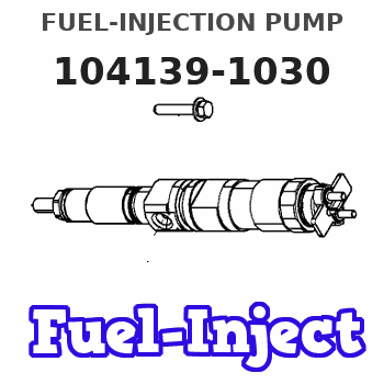
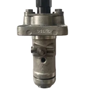
Information fuel-injection pump
BOSCH
9 410 618 072
9410618072
ZEXEL
104139-1030
1041391030
ISUZU
8973519850
8973519850
Rating:
Compare Prices: .
As an associate, we earn commssions on qualifying purchases through the links below

High Pressure Oil Pump 8-97351985-0 897351-9850 104139-1030 PW16 4LE2 SK75-8 SY75-8 Fuel Injection Pump, Compatible with Isuzu
JIEBMEI High Pressure Oil Pump 8-97351985-0 897351-9850 104139-1030 PW16 4LE2 SK75-8 SY75-8 Fuel Injection Pump, Compatible with Isuzu || Economical and energy-saving, precisely supply fuel to optimize combustion, combined with electronic control technology, actively adjust flow to reduce fuel consumption || Environmental protection and emission reduction, precise control of fuel supply, help reduce vehicle exhaust emissions, and better comply with environmental protection regulations || The operation is stable, ensuring the smooth running of the engine under different driving conditions such as acceleration, deceleration and climbing || Reliable pressure limiting, with an internal pressure limiting valve. When the system pressure is too high, it automatically opens the return oil path to avoid the risk of overpressure
JIEBMEI High Pressure Oil Pump 8-97351985-0 897351-9850 104139-1030 PW16 4LE2 SK75-8 SY75-8 Fuel Injection Pump, Compatible with Isuzu || Economical and energy-saving, precisely supply fuel to optimize combustion, combined with electronic control technology, actively adjust flow to reduce fuel consumption || Environmental protection and emission reduction, precise control of fuel supply, help reduce vehicle exhaust emissions, and better comply with environmental protection regulations || The operation is stable, ensuring the smooth running of the engine under different driving conditions such as acceleration, deceleration and climbing || Reliable pressure limiting, with an internal pressure limiting valve. When the system pressure is too high, it automatically opens the return oil path to avoid the risk of overpressure
You can express buy:
USD 200
28-05-2025
28-05-2025
High Pressure Diesel Fuel Injection Pump for 9410618072 ZEXEL 104139-1030 1041391030 ISUZU 8973519850
Components :
| 0. | INJECTION-PUMP ASSEMBLY | 104139-1030 |
| 1. | _ | |
| 2. | FUEL INJECTION PUMP | |
| 3. | NUMBER PLATE | |
| 4. | _ | |
| 5. | CAPSULE | |
| 6. | ADJUSTING DEVICE | |
| 7. | NOZZLE AND HOLDER ASSY | 105118-8340 |
| 8. | Nozzle and Holder | |
| 9. | Open Pre:MPa(Kqf/cm2) | 16.7{170}/25.0{255} |
| 10. | NOZZLE-HOLDER | 105048-2250 |
| 11. | NOZZLE | 105017-3420 |
Scheme ###:
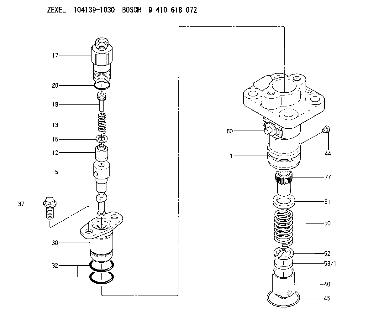
| 1. | [1] | 140051-9100 | PUMP HOUSING |
| 5. | [1] | 140163-3820 | PLUNGER-AND-BARREL ASSY |
| 12. | [1] | 140110-6020 | DELIVERY-VALVE ASSEMBLY |
| 13. | [1] | 140112-3400 | COMPRESSION SPRING |
| 16. | [1] | 140115-1400 | GASKET |
| 17. | [1] | 140116-7120 | FITTING |
| 18. | [1] | 140117-1700 | FILLER PIECE |
| 20. | [1] | 140118-0301 | O-RING |
| 30. | [1] | 140131-0421 | FLANGE BUSHING |
| 32. | [2] | 140118-0201 | O-RING |
| 37. | [2] | 140124-0200 | BLEEDER SCREW |
| 40. | [1] | 140200-2620 | TAPPET |
| 44. | [1] | 140212-0500 | BEARING PIN |
| 45. | [1] | 140213-1800 | LOCKING WASHER |
| 50. | [1] | 140215-1900 | COMPRESSION SPRING |
| 51. | [1] | 140216-0800 | SLOTTED WASHER |
| 52. | [1] | 140217-2200 | SLOTTED WASHER |
| 53/1. | [1] | 140217-5000 | PLATE D19T2.60 |
| 53/1. | [1] | 140217-5100 | PLATE D19T2.65 |
| 53/1. | [1] | 140217-5200 | PLATE D19T2.70 |
| 53/1. | [1] | 140217-5300 | PLATE D19T2.75 |
| 53/1. | [1] | 140217-5400 | PLATE D19T2.80 |
| 53/1. | [1] | 140217-5500 | PLATE D19T2.85 |
| 53/1. | [1] | 140217-5600 | PLATE D19T2.90 |
| 53/1. | [1] | 140217-5700 | PLATE D19T2.95 |
| 53/1. | [1] | 140217-5800 | PLATE D19T3.00 |
| 53/1. | [1] | 140217-5900 | PLATE D19T3.05 |
| 53/1. | [1] | 140217-6000 | PLATE D19T3.10 |
| 53/1. | [1] | 140217-6100 | PLATE D19T3.15 |
| 53/1. | [1] | 140217-6200 | PLATE D19T3.20 |
| 53/1. | [1] | 140217-6300 | PLATE D19T3.25 |
| 53/1. | [1] | 140217-6400 | PLATE D19T3.30 |
| 53/1. | [1] | 140217-6500 | PLATE D19T3.35 |
| 53/1. | [1] | 140217-6600 | PLATE D19T3.40 |
| 53/1. | [1] | 140217-6700 | PLATE D19T3.45 |
| 53/1. | [1] | 140217-6800 | PLATE D19T3.50 |
| 53/1. | [1] | 140217-6900 | PLATE D19T3.55 |
| 53/1. | [1] | 140217-7000 | PLATE D19T3.60 |
| 53/1. | [1] | 140217-7100 | PLATE D19T3.65 |
| 53/1. | [1] | 140217-7200 | PLATE D19T3.70 |
| 53/1. | [1] | 140217-7300 | PLATE D19T3.75 |
| 53/1. | [1] | 140217-7400 | PLATE D19T3.80 |
| 53/1. | [1] | 140217-7500 | PLATE D19T3.85 |
| 53/1. | [1] | 140217-7600 | PLATE D19T3.90 |
| 53/1. | [1] | 140217-7700 | PLATE D19T3.95 |
| 53/1. | [1] | 140217-7800 | PLATE D19T4.00 |
| 53/1. | [1] | 140217-7900 | PLATE D19T4.05 |
| 53/1. | [1] | 140217-8000 | PLATE D19T4.10 |
| 53/1. | [1] | 140253-2000 | PLATE |
| 53/1. | [1] | 140253-2100 | PLATE |
| 53/1. | [1] | 140253-2200 | PLATE |
| 53/1. | [1] | 140253-2300 | PLATE |
| 53/1. | [1] | 140253-2400 | PLATE |
| 53/1. | [1] | 140253-2500 | PLATE |
| 53/1. | [1] | 140253-2600 | PLATE |
| 53/1. | [1] | 140253-2700 | PLATE |
| 53/1. | [1] | 140253-2800 | PLATE |
| 53/1. | [1] | 140253-2900 | PLATE |
| 53/1. | [1] | 140253-3000 | PLATE |
| 53/1. | [1] | 140253-3100 | PLATE |
| 53/1. | [1] | 140253-3200 | PLATE |
| 53/1. | [1] | 140253-3300 | PLATE |
| 53/1. | [1] | 140253-3400 | PLATE |
| 53/1. | [1] | 140253-3500 | PLATE |
| 53/1. | [1] | 140253-3600 | PLATE |
| 53/1. | [1] | 140253-3700 | PLATE |
| 53/1. | [1] | 140253-3800 | PLATE |
| 53/1. | [1] | 140253-3900 | PLATE |
| 53/1. | [1] | 140253-4000 | PLATE |
| 53/1. | [1] | 140253-4100 | PLATE |
| 53/1. | [1] | 140253-4200 | PLATE |
| 53/1. | [1] | 140253-4300 | PLATE |
| 53/1. | [1] | 140253-4400 | PLATE |
| 53/1. | [1] | 140253-4500 | PLATE |
| 53/1. | [1] | 140253-4600 | PLATE |
| 53/1. | [1] | 140253-4700 | PLATE |
| 53/1. | [1] | 140253-4800 | PLATE |
| 53/1. | [1] | 140253-4900 | PLATE |
| 60. | [1] | 140243-6423 | CONTROL RACK |
| 77. | [1] | 140241-4200 | CONTROL SLEEVE |
Include in #1:
106873-2920
as _
Include in #2:
104139-1030
as INJECTION-PUMP ASSEMBLY
Cross reference number
Zexel num
Bosch num
Firm num
Name
104139-1030
8973519850 ISUZU
FUEL-INJECTION PUMP
K 23AA FUEL INJECTION PUMP PFR-1KX PFR
K 23AA FUEL INJECTION PUMP PFR-1KX PFR
Information:
2. Disconnect air compressor line (2) and fuel ratio control line (3) from the aftercooler housing.3. Remove four bolts (1), nuts and cover that connect the inlet pipe to the aftercooler housing. 4. Put a mark on the turbocharger compressor housing in alignment with a mark on the turbocharger cartridge housing. Loosen the bolts for the turbocharger compressor housing. Turn the housing so air inlet pipe (4) is away from the aftercooler housing.5. Remove bolts (5) that hold the aftercooler housing to the cylinder head.6. Fasten a hoist to the aftercooler housing and remove the aftercooler housing from the engine. Weight is 95 lb. (43 kg).Install Aftercooler Housing
1. Install new O-ring seals on the aftercooler water inlet and outlet pipes. 2. Fasten a hoist to aftercooler housing (1) and put the aftercooler housing in position on the water pipes and cylinder head.3. Put 9S3263 Thread Lock on the threads of the bolts and install the bolts that hold the aftercooler housing to the cylinder head. 4. Turn the turbocharger compressor housing carefully so the mark on the housing is in alignment with the mark on the turbocharger cartridge housing. Tighten bolts (2) for the compressor housing to 105 5 lb.in. (11.9 0.6 N m).
Do not cause damage to the O-ring seal between the turbocharger compressor housing and the cartridge housing.
5. Install the four bolts and nuts that connect the air inlet pipe to the aftercooler housing.6. Connect the air compressor line and fuel ratio control line.7. Fill engine with coolant.end by:a) install fuel filter base