Information fuel-injection pump
BOSCH
9 410 617 901
9410617901
ZEXEL
104139-1011
1041391011
ISUZU
8972293682
8972293682
Rating:
Compare Prices: .
As an associate, we earn commssions on qualifying purchases through the links below

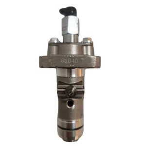
Fuel Injection Pump 104139-1040 8972293682 for Isuzu Engine 4LE1 4LE2 Hitachi Carrier EG30
FGNTWP Part Number:9 410 617 901, 9410617901, 104139-1011, 1041391011, 8972293682, 8972293680, 8972293681, F 01G 09Y 01A, F01G09Y01A, 104139-1040, 1041391040, 8980965800, 8980965801, 8-97229368-2, 8-97229368-0, 8-97229368-1, 8-98096580-0, 8-98096580-1, 8-97229-368-2, 8-97229-368-0, 8-97229-368-1, 8-98096-580-0, 8-98096-580-1, 104139-1010, 1041391010, 9 410 618 157, 9410618157 || Application:Fit for Hitachi Rubber Crawler Carrier:EG30
FGNTWP Part Number:9 410 617 901, 9410617901, 104139-1011, 1041391011, 8972293682, 8972293680, 8972293681, F 01G 09Y 01A, F01G09Y01A, 104139-1040, 1041391040, 8980965800, 8980965801, 8-97229368-2, 8-97229368-0, 8-97229368-1, 8-98096580-0, 8-98096580-1, 8-97229-368-2, 8-97229-368-0, 8-97229-368-1, 8-98096-580-0, 8-98096-580-1, 104139-1010, 1041391010, 9 410 618 157, 9410618157 || Application:Fit for Hitachi Rubber Crawler Carrier:EG30

Congparts Fuel Injection Pump 9410617901 104139-1011 1041391011 8972293682 8972293680 F01G09Y01A Compatible with Isuzu Engine 4LE1 4LE2 Compatible with Hitachi Crawler Carrier EG30
Congparts Part Number: 9 410 617 901 9410617901 104139-1011 1041391011 8972293682 8972293680 8972293681 F 01G 09Y 01A F01G09Y01A 104139-1040 1041391040 8980965800 8980965801 8-97229368-2 8-97229368-0 8-97229368-1 8-98096580-0 8-98096580-1 8-97229-368-2 8-97229-368-0 8-97229-368-1 8-98096-580-0 8-98096-580-1 104139-1010 1041391010 9 410 618 157 9410618157 || Compatible with Isuzu Engine 4LE1 4LE2 Compatible with Hitachi Crawler Carrier EG30 || Package Included: 1 x Fuel Injection Pump || Easy Installation.Stable Characteristics High Reliability || It Is a Replacement Part Not Original Part. But It Can Work Good For You
Congparts Part Number: 9 410 617 901 9410617901 104139-1011 1041391011 8972293682 8972293680 8972293681 F 01G 09Y 01A F01G09Y01A 104139-1040 1041391040 8980965800 8980965801 8-97229368-2 8-97229368-0 8-97229368-1 8-98096580-0 8-98096580-1 8-97229-368-2 8-97229-368-0 8-97229-368-1 8-98096-580-0 8-98096-580-1 104139-1010 1041391010 9 410 618 157 9410618157 || Compatible with Isuzu Engine 4LE1 4LE2 Compatible with Hitachi Crawler Carrier EG30 || Package Included: 1 x Fuel Injection Pump || Easy Installation.Stable Characteristics High Reliability || It Is a Replacement Part Not Original Part. But It Can Work Good For You

You can express buy:
USD 260
19-05-2025
19-05-2025
Fuel Injection Pump 104139-1040 8972293682 for Isuzu Engine 4LE1 4LE2 4LB1 4LD1 for Hitachi for Carrier EG30
Components :
| 0. | INJECTION-PUMP ASSEMBLY | 104139-1011 |
| 1. | _ | |
| 2. | FUEL INJECTION PUMP | |
| 3. | NUMBER PLATE | |
| 4. | _ | |
| 5. | CAPSULE | |
| 6. | ADJUSTING DEVICE | |
| 7. | NOZZLE AND HOLDER ASSY | 105118-6771 |
| 8. | Nozzle and Holder | |
| 9. | Open Pre:MPa(Kqf/cm2) | 17.7{180} |
| 10. | NOZZLE-HOLDER | 105048-2260 |
| 11. | NOZZLE | 105017-2840 |
Scheme ###:
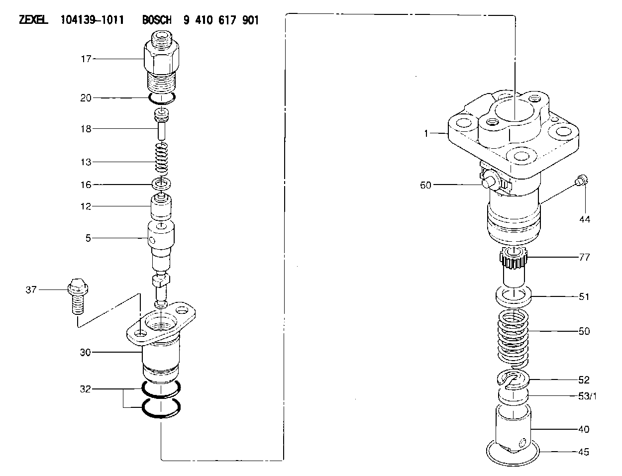
| 1. | [1] | 140051-9100 | PUMP HOUSING |
| 5. | [1] | 140163-1920 | PLUNGER-AND-BARREL ASSY |
| 12. | [1] | 140110-5320 | DELIVERY-VALVE ASSEMBLY |
| 13. | [1] | 140112-2900 | COMPRESSION SPRING |
| 16. | [1] | 140115-1400 | GASKET |
| 17. | [1] | 140116-7120 | FITTING |
| 18. | [1] | 140117-1700 | FILLER PIECE |
| 20. | [1] | 140118-0301 | O-RING |
| 30. | [1] | 140131-0421 | FLANGE BUSHING |
| 32. | [2] | 140118-0201 | O-RING |
| 37. | [2] | 140124-0200 | BLEEDER SCREW |
| 40. | [1] | 140200-2620 | TAPPET |
| 44. | [1] | 140212-0500 | BEARING PIN |
| 45. | [1] | 140213-1800 | LOCKING WASHER |
| 50. | [1] | 140215-1900 | COMPRESSION SPRING |
| 51. | [1] | 140216-0800 | SLOTTED WASHER |
| 52. | [1] | 140217-2200 | SLOTTED WASHER |
| 53/1. | [1] | 140217-5000 | PLATE D19T2.60 |
| 53/1. | [1] | 140217-5100 | PLATE D19T2.65 |
| 53/1. | [1] | 140217-5200 | PLATE D19T2.70 |
| 53/1. | [1] | 140217-5300 | PLATE D19T2.75 |
| 53/1. | [1] | 140217-5400 | PLATE D19T2.80 |
| 53/1. | [1] | 140217-5500 | PLATE D19T2.85 |
| 53/1. | [1] | 140217-5600 | PLATE D19T2.90 |
| 53/1. | [1] | 140217-5700 | PLATE D19T2.95 |
| 53/1. | [1] | 140217-5800 | PLATE D19T3.00 |
| 53/1. | [1] | 140217-5900 | PLATE D19T3.05 |
| 53/1. | [1] | 140217-6000 | PLATE D19T3.10 |
| 53/1. | [1] | 140217-6100 | PLATE D19T3.15 |
| 53/1. | [1] | 140217-6200 | PLATE D19T3.20 |
| 53/1. | [1] | 140217-6300 | PLATE D19T3.25 |
| 53/1. | [1] | 140217-6400 | PLATE D19T3.30 |
| 53/1. | [1] | 140217-6500 | PLATE D19T3.35 |
| 53/1. | [1] | 140217-6600 | PLATE D19T3.40 |
| 53/1. | [1] | 140217-6700 | PLATE D19T3.45 |
| 53/1. | [1] | 140217-6800 | PLATE D19T3.50 |
| 53/1. | [1] | 140217-6900 | PLATE D19T3.55 |
| 53/1. | [1] | 140217-7000 | PLATE D19T3.60 |
| 53/1. | [1] | 140217-7100 | PLATE D19T3.65 |
| 53/1. | [1] | 140217-7200 | PLATE D19T3.70 |
| 53/1. | [1] | 140217-7300 | PLATE D19T3.75 |
| 53/1. | [1] | 140217-7400 | PLATE D19T3.80 |
| 53/1. | [1] | 140217-7500 | PLATE D19T3.85 |
| 53/1. | [1] | 140217-7600 | PLATE D19T3.90 |
| 53/1. | [1] | 140217-7700 | PLATE D19T3.95 |
| 53/1. | [1] | 140217-7800 | PLATE D19T4.00 |
| 53/1. | [1] | 140217-7900 | PLATE D19T4.05 |
| 53/1. | [1] | 140217-8000 | PLATE D19T4.10 |
| 53/1. | [1] | 140253-2000 | PLATE |
| 53/1. | [1] | 140253-2100 | PLATE |
| 53/1. | [1] | 140253-2200 | PLATE |
| 53/1. | [1] | 140253-2300 | PLATE |
| 53/1. | [1] | 140253-2400 | PLATE |
| 53/1. | [1] | 140253-2500 | PLATE |
| 53/1. | [1] | 140253-2600 | PLATE |
| 53/1. | [1] | 140253-2700 | PLATE |
| 53/1. | [1] | 140253-2800 | PLATE |
| 53/1. | [1] | 140253-2900 | PLATE |
| 53/1. | [1] | 140253-3000 | PLATE |
| 53/1. | [1] | 140253-3100 | PLATE |
| 53/1. | [1] | 140253-3200 | PLATE |
| 53/1. | [1] | 140253-3300 | PLATE |
| 53/1. | [1] | 140253-3400 | PLATE |
| 53/1. | [1] | 140253-3500 | PLATE |
| 53/1. | [1] | 140253-3600 | PLATE |
| 53/1. | [1] | 140253-3700 | PLATE |
| 53/1. | [1] | 140253-3800 | PLATE |
| 53/1. | [1] | 140253-3900 | PLATE |
| 53/1. | [1] | 140253-4000 | PLATE |
| 53/1. | [1] | 140253-4100 | PLATE |
| 53/1. | [1] | 140253-4200 | PLATE |
| 53/1. | [1] | 140253-4300 | PLATE |
| 53/1. | [1] | 140253-4400 | PLATE |
| 53/1. | [1] | 140253-4500 | PLATE |
| 53/1. | [1] | 140253-4600 | PLATE |
| 53/1. | [1] | 140253-4700 | PLATE |
| 53/1. | [1] | 140253-4800 | PLATE |
| 53/1. | [1] | 140253-4900 | PLATE |
| 60. | [1] | 140243-6422 | CONTROL RACK |
| 77. | [1] | 140241-2700 | CONTROL SLEEVE |
Include in #1:
106873-2900
as _
Include in #2:
104139-1011
as INJECTION-PUMP ASSEMBLY
Cross reference number
Zexel num
Bosch num
Firm num
Name
104139-1011
8972293682 ISUZU
FUEL-INJECTION PUMP
K 23AA FUEL INJECTION PUMP PFR-1KX PFR
K 23AA FUEL INJECTION PUMP PFR-1KX PFR
Information:
start by:a) separation of governor from fuel injection pump housing 1. Remove the ring (3) and pin (1) that hold seat (2). 2. Remove seat (2), bolt (4), washers (6) and spring (5).3. Remove the sleeve and bearing assembly from the cylinder and weight assemblies. 4. Remove ring (7) from sleeve (8).5. Remove bearing (9) and washers (10) from sleeve (8). 6. Remove valve (12) from piston (11). 7. Remove ring (15) that holds the weight assembly to cylinder (16).8. Remove weight assembly (13) from the cylinder.9. Remove piston (11) and sleeve (14) from the cylinder. Remove the O-ring seal from sleeve (14). 10. Remove speed limiter plug (20), spring and plunger from the governor housing (19).11. Remove torque spring assembly (17). 12. Remove bolt (21) and lock that hold lever (22) to shaft (18).13. Remove lever (22) and shaft from the housing.14. Remove the seal from housing (19).15. Remove the bearings and plug from the housing with tooling (A). 16. Remove two bolts (23), lock, lever arm (26) and shaft (25) from idle screw housing (24).17. Remove the two seals, bearings and plug from housing (24) with tooling (A).Assemble Governor
1. Use tooling (A) to install inner seal (3) in idle screw housing (2). Install seal (3) so the lip of the seal is toward bearing (4). Put clean engine oil on the lips of the seals.2. Use tooling (A) to install bearing (1) and the outer seal. Install the outer seal with the lip of the seal toward the outside. Install bearing (4). 3. Install bearing (6) in governor housing (8) to dimension (Y) or .897 .010 in. (22.97 0.25 mm) with tooling (A). Install bearing (5) in the governor housing to dimension (X) or 2.385 .005 in. (60.58 0.13 mm) from bearing (6). Install plug (7) in the governor housing. 4. Use tooling (A) to install the seal in governor housing (8). Install the seal with the lip of the seal toward the inside.5. Install torque spring assembly (9) on the governor housing. Install the lock and bolts that hold it. See RACK SETTING INFORMATION for the correct adjustment of the torque spring assembly. 6. Put lever assembly (11) in position in the governor housing. Install shaft (10) in the housing through the lever. Install the lock and bolt that hold the lever to the shaft. 7. Install speed limiter plunger (14), spring (13) and plug (12) in the governor housing. 8. Install O-ring seal (17) on sleeve (18).9. Install piston (16) and the sleeve in cylinder (15). 10. Put weight assembly (19) on cylinder (15). Install the ring that holds the weight assembly on the cylinder. 11. Install valve (21) in piston (16).12. Install bearing and washers (22) on sleeve (20). Install the ring that holds the washers and bearing on the sleeve.13. Install the sleeve assembly on valve (21). 14. Install bolt (23) in seat (24). Install the washers and spring in the seat.15. Put the seat in position on
1. Use tooling (A) to install inner seal (3) in idle screw housing (2). Install seal (3) so the lip of the seal is toward bearing (4). Put clean engine oil on the lips of the seals.2. Use tooling (A) to install bearing (1) and the outer seal. Install the outer seal with the lip of the seal toward the outside. Install bearing (4). 3. Install bearing (6) in governor housing (8) to dimension (Y) or .897 .010 in. (22.97 0.25 mm) with tooling (A). Install bearing (5) in the governor housing to dimension (X) or 2.385 .005 in. (60.58 0.13 mm) from bearing (6). Install plug (7) in the governor housing. 4. Use tooling (A) to install the seal in governor housing (8). Install the seal with the lip of the seal toward the inside.5. Install torque spring assembly (9) on the governor housing. Install the lock and bolts that hold it. See RACK SETTING INFORMATION for the correct adjustment of the torque spring assembly. 6. Put lever assembly (11) in position in the governor housing. Install shaft (10) in the housing through the lever. Install the lock and bolt that hold the lever to the shaft. 7. Install speed limiter plunger (14), spring (13) and plug (12) in the governor housing. 8. Install O-ring seal (17) on sleeve (18).9. Install piston (16) and the sleeve in cylinder (15). 10. Put weight assembly (19) on cylinder (15). Install the ring that holds the weight assembly on the cylinder. 11. Install valve (21) in piston (16).12. Install bearing and washers (22) on sleeve (20). Install the ring that holds the washers and bearing on the sleeve.13. Install the sleeve assembly on valve (21). 14. Install bolt (23) in seat (24). Install the washers and spring in the seat.15. Put the seat in position on