Information fuel-injection pump
BOSCH
9 410 618 373
9410618373
ZEXEL
104138-4001
1041384001
ISEKI
62156001320B
62156001320b

Rating:
Compare Prices: .
As an associate, we earn commssions on qualifying purchases through the links below

WZCNLXLX Fuel Injection Pump 104138-4001 62156001320 9410618373 For Perkins 700 Series
WZCNLXLX Item Name:Fuel Injection Pump || Item Number:104138-4001 62156001320 9410618373 || Application:For Perkins 700 Series || Note: If you are unsure if the product is suitable.In order not to delay your use of the parts, please provide your engine nameplate or serial number and part number, and we will help you confirm if it is suitable. To avoid unnecessary returns, please check the product image and part number to ensure it is the product you want. || Tip: Please contact us - we are a professional sales team and we have many products to offer to you. Many buyers are very satisfied with our service. You can get first-class products and high-quality services from us, believe me, you will have a pleasant shopping experience here.
WZCNLXLX Item Name:Fuel Injection Pump || Item Number:104138-4001 62156001320 9410618373 || Application:For Perkins 700 Series || Note: If you are unsure if the product is suitable.In order not to delay your use of the parts, please provide your engine nameplate or serial number and part number, and we will help you confirm if it is suitable. To avoid unnecessary returns, please check the product image and part number to ensure it is the product you want. || Tip: Please contact us - we are a professional sales team and we have many products to offer to you. Many buyers are very satisfied with our service. You can get first-class products and high-quality services from us, believe me, you will have a pleasant shopping experience here.

Components :
| 0. | INJECTION-PUMP ASSEMBLY | 104138-4001 |
| 1. | _ | |
| 2. | FUEL INJECTION PUMP | |
| 3. | NUMBER PLATE | |
| 4. | _ | |
| 5. | CAPSULE | |
| 6. | ADJUSTING DEVICE | |
| 7. | NOZZLE AND HOLDER ASSY | 105148-1363 |
| 8. | Nozzle and Holder | |
| 9. | Open Pre:MPa(Kqf/cm2) | 11.8(120) |
| 10. | NOZZLE-HOLDER | 105078-0211 |
| 11. | NOZZLE | 105007-1330 |
Scheme ###:
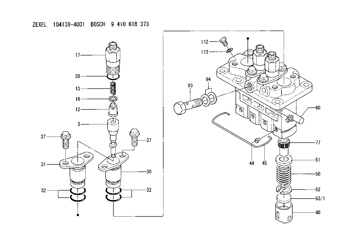
| 5. | [4] | 140163-4320 | PLUNGER-AND-BARREL ASSY |
| 12. | [4] | 140110-4820 | DELIVERY-VALVE ASSEMBLY |
| 13. | [4] | 140112-3400 | COMPRESSION SPRING |
| 16. | [4] | 140115-1400 | GASKET |
| 17. | [4] | 140116-7520 | FITTING |
| 20. | [4] | 140118-0301 | O-RING |
| 30. | [3] | 140131-0521 | FLANGE BUSHING |
| 31. | [1] | 140131-1021 | FLANGE BUSHING |
| 32. | [8] | 140118-0201 | O-RING |
| 32. | [8] | 140118-0201 | O-RING |
| 37. | [8] | 140124-0200 | BLEEDER SCREW |
| 37. | [8] | 140124-0200 | BLEEDER SCREW |
| 40. | [4] | 140200-1620 | TAPPET |
| 44. | [4] | 140212-0300 | BEARING PIN |
| 45. | [1] | 140213-1500 | LOCKING WASHER |
| 50. | [4] | 140215-1900 | COMPRESSION SPRING |
| 51. | [4] | 140216-0800 | SLOTTED WASHER |
| 52. | [4] | 140217-2200 | SLOTTED WASHER |
| 53/1. | [1] | 140217-5000 | PLATE D19T2.60 |
| 53/1. | [1] | 140217-5100 | PLATE D19T2.65 |
| 53/1. | [1] | 140217-5200 | PLATE D19T2.70 |
| 53/1. | [1] | 140217-5300 | PLATE D19T2.75 |
| 53/1. | [1] | 140217-5400 | PLATE D19T2.80 |
| 53/1. | [1] | 140217-5500 | PLATE D19T2.85 |
| 53/1. | [1] | 140217-5600 | PLATE D19T2.90 |
| 53/1. | [1] | 140217-5700 | PLATE D19T2.95 |
| 53/1. | [1] | 140217-5800 | PLATE D19T3.00 |
| 53/1. | [1] | 140217-5900 | PLATE D19T3.05 |
| 53/1. | [1] | 140217-6000 | PLATE D19T3.10 |
| 53/1. | [1] | 140217-6100 | PLATE D19T3.15 |
| 53/1. | [1] | 140217-6200 | PLATE D19T3.20 |
| 53/1. | [1] | 140217-6300 | PLATE D19T3.25 |
| 53/1. | [1] | 140217-6400 | PLATE D19T3.30 |
| 53/1. | [1] | 140217-6500 | PLATE D19T3.35 |
| 53/1. | [1] | 140217-6600 | PLATE D19T3.40 |
| 53/1. | [1] | 140217-6700 | PLATE D19T3.45 |
| 53/1. | [1] | 140217-6800 | PLATE D19T3.50 |
| 53/1. | [1] | 140217-6900 | PLATE D19T3.55 |
| 53/1. | [1] | 140217-7000 | PLATE D19T3.60 |
| 53/1. | [1] | 140217-7100 | PLATE D19T3.65 |
| 53/1. | [1] | 140217-7200 | PLATE D19T3.70 |
| 53/1. | [1] | 140217-7300 | PLATE D19T3.75 |
| 53/1. | [1] | 140217-7400 | PLATE D19T3.80 |
| 53/1. | [1] | 140217-7500 | PLATE D19T3.85 |
| 53/1. | [1] | 140217-7600 | PLATE D19T3.90 |
| 53/1. | [1] | 140217-7700 | PLATE D19T3.95 |
| 53/1. | [1] | 140217-7800 | PLATE D19T4.00 |
| 53/1. | [1] | 140217-7900 | PLATE D19T4.05 |
| 53/1. | [1] | 140217-8000 | PLATE D19T4.10 |
| 53/1. | [1] | 140253-2000 | PLATE |
| 53/1. | [1] | 140253-2100 | PLATE |
| 53/1. | [1] | 140253-2200 | PLATE |
| 53/1. | [1] | 140253-2300 | PLATE |
| 53/1. | [1] | 140253-2400 | PLATE |
| 53/1. | [1] | 140253-2500 | PLATE |
| 53/1. | [1] | 140253-2600 | PLATE |
| 53/1. | [1] | 140253-2700 | PLATE |
| 53/1. | [1] | 140253-2800 | PLATE |
| 53/1. | [1] | 140253-2900 | PLATE |
| 53/1. | [1] | 140253-3000 | PLATE |
| 53/1. | [1] | 140253-3100 | PLATE |
| 53/1. | [1] | 140253-3200 | PLATE |
| 53/1. | [1] | 140253-3300 | PLATE |
| 53/1. | [1] | 140253-3400 | PLATE |
| 53/1. | [1] | 140253-3500 | PLATE |
| 53/1. | [1] | 140253-3600 | PLATE |
| 53/1. | [1] | 140253-3700 | PLATE |
| 53/1. | [1] | 140253-3800 | PLATE |
| 53/1. | [1] | 140253-3900 | PLATE |
| 53/1. | [1] | 140253-4000 | PLATE |
| 53/1. | [1] | 140253-4100 | PLATE |
| 53/1. | [1] | 140253-4200 | PLATE |
| 53/1. | [1] | 140253-4300 | PLATE |
| 53/1. | [1] | 140253-4400 | PLATE |
| 53/1. | [1] | 140253-4500 | PLATE |
| 53/1. | [1] | 140253-4600 | PLATE |
| 53/1. | [1] | 140253-4700 | PLATE |
| 53/1. | [1] | 140253-4800 | PLATE |
| 53/1. | [1] | 140253-4900 | PLATE |
| 60. | [1] | 140243-6520 | CONTROL RACK |
| 77. | [4] | 140241-2700 | CONTROL SLEEVE |
| 93. | [1] | 027412-2440 | EYE BOLT |
| 94. | [2] | 026512-1540 | GASKET D15.4&12.2T1.50 |
| 112. | [1] | 140420-1400 | BLEEDER SCREW |
| 113. | [1] | 026508-1240 | GASKET D11.9&8.2T1 |
Include in #1:
106873-2870
as _
Include in #2:
104138-4001
as INJECTION-PUMP ASSEMBLY
Cross reference number
Zexel num
Bosch num
Firm num
Name
104138-4001
62156001320B ISEKI
FUEL-INJECTION PUMP
K 23AD FUEL INJECTION PUMP PFR-4KX PFR
K 23AD FUEL INJECTION PUMP PFR-4KX PFR
Information:
Remove Fuel Ratio Control
1. Disconnect line (1) from the fuel ratio control.2. Remove the wire seal from the bolts.3. Remove two bolts (2). Remove fuel ratio control (3) after it is moved down and out from the collar.Install Fuel Ratio Control
1. Put the fuel ratio control on the governor. 2. Be sure bolt (2) of the fuel ratio control is connected in the groove of collar (1).3. Install the two bolts that hold the fuel ratio control on the governor.4. Connect the line to the fuel ratio control.5. Install a wire seal on the bolts.Disassemble Fuel Ratio Control
start by:a) remove fuel ratio control 1. Remove the bolts and the housing (1).2. Remove wire seal (2) from the bolts. 3. Remove valve assembly (3).4. Remove seal (4) and O-ring seal from valve.5. Remove the retainer (5) and two springs (6). 6. Remove three bolts (9) and cover (10).7. Remove valve (7), diaphragm (8), retainer and spring. 8. Remove pin (12) from valve (7).9. Remove cover (11) from the valve.10. Remove the seal from the cover (11).Assemble Fuel Ratio Control
1. Put clean engine oil on lip of seal. Install the seal (1) in cover (2). Install seal so lip of seal is toward the inside of the cover. 2. Install the valve (3) into cover (2).3. Install the pin that holds cover on valve. 4. Install spring (7) and the retainer (6) in cover (8).5. Install diaphragm (5) on the valve assembly (4) and in the cover. 6. Install cover and three bolts (11) that hold covers together. Install wire seal on the bolts with tool group (A) after the fuel ratio control is installed and adjustments are made to it.7. Put clean engine oil on seal and ring seal. Install the seals (1) on valve.8. Install the two springs (13), retainer, and valve assembly (12).9. Install housing (9) and two bolts.end by: a) install fuel ratio control