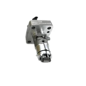
Information fuel-injection pump
BOSCH
9 410 618 096
9410618096
ZEXEL
104136-1022
1041361022
ISUZU
8971475801
8971475801

Rating:
Compare Prices: .
As an associate, we earn commssions on qualifying purchases through the links below

Fuel Injection Pump 8-97147580-1 8971475801 Compatible with Isuzu 4LE1 Engine
DJCXYSM Product Name:Fuel Injection Pump || Part Number:8-97147580-1 8971475801 || Application:Compatible with Isuzu 4LE1 Engine || NOTE: To avoid unnecessary returns please check the part number before purchasing or tell us the picture of your engine model and nameplate to reduce the error rate. || Tip: Please purchase according to the part number, as there may be discrepancies between the pictures and the actual product.
DJCXYSM Product Name:Fuel Injection Pump || Part Number:8-97147580-1 8971475801 || Application:Compatible with Isuzu 4LE1 Engine || NOTE: To avoid unnecessary returns please check the part number before purchasing or tell us the picture of your engine model and nameplate to reduce the error rate. || Tip: Please purchase according to the part number, as there may be discrepancies between the pictures and the actual product.

CARTEX Fuel Injection Pump 8971475801 for FITS Isuzu Engine 3LD1 3LD2 4LB1 4LC1 4LE1 FITS HITACHI EX40U EX50U EX50UNA EX55UR-3
CARTEX Whether you're a professional mechanic or a DIY enthusiast,We've got you covered with a wide range of parts that meet the highest standards of quality and performance. || Order your High Quality Part with peace of mind, knowing we prioritize your satisfaction. Quality Parts, Superior Performance - it's not just a promise, it's our standard || QUESTIONS? : We at CARTEX - High Quality Parts USA has more than 40 years of experience in industry and has in-house technicians, If you are not sure if this part fits your machine or tractor, just send us an email before you make the purchase and our in house technicians will revert back to you, right away.
CARTEX Whether you're a professional mechanic or a DIY enthusiast,We've got you covered with a wide range of parts that meet the highest standards of quality and performance. || Order your High Quality Part with peace of mind, knowing we prioritize your satisfaction. Quality Parts, Superior Performance - it's not just a promise, it's our standard || QUESTIONS? : We at CARTEX - High Quality Parts USA has more than 40 years of experience in industry and has in-house technicians, If you are not sure if this part fits your machine or tractor, just send us an email before you make the purchase and our in house technicians will revert back to you, right away.

You can express buy:
USD 289.57
19-05-2025
19-05-2025
For 4LE2 4LE1 Kobelco 75-8 Diesel Pump Unit Pump 8971475801 104130-1001 Mixer Truck Oil Pump Plunger PVC Valve 094150-0618
Components :
| 0. | INJECTION-PUMP ASSEMBLY | 104136-1022 |
| 1. | _ | |
| 2. | FUEL INJECTION PUMP | |
| 3. | NUMBER PLATE | |
| 4. | _ | |
| 5. | CAPSULE | |
| 6. | ADJUSTING DEVICE | |
| 7. | NOZZLE AND HOLDER ASSY | 105148-1271 |
| 8. | Nozzle and Holder | |
| 9. | Open Pre:MPa(Kqf/cm2) | 13.2{135} |
| 10. | NOZZLE-HOLDER | 105078-0171 |
| 11. | NOZZLE | 105007-1010 |
Scheme ###:
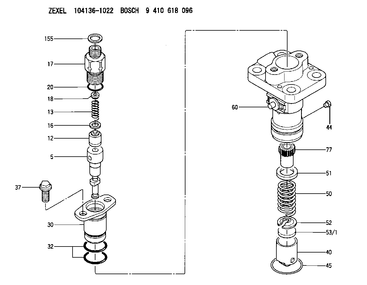
| 5. | [1] | 140163-0320 | PLUNGER-AND-BARREL ASSY |
| 12. | [1] | 140110-3720 | DELIVERY-VALVE ASSEMBLY |
| 13. | [1] | 140112-1700 | COMPRESSION SPRING |
| 16. | [1] | 140115-1400 | GASKET |
| 17. | [1] | 140116-7600 | FITTING |
| 18. | [1] | 140117-1800 | SLOTTED WASHER |
| 20. | [1] | 140118-0301 | O-RING |
| 30. | [1] | 140131-0421 | FLANGE BUSHING |
| 32. | [2] | 140118-0201 | O-RING |
| 37. | [2] | 140124-0200 | BLEEDER SCREW |
| 40. | [1] | 140200-1620 | TAPPET |
| 44. | [1] | 140212-0500 | BEARING PIN |
| 45. | [1] | 140213-1800 | LOCKING WASHER |
| 50. | [1] | 140215-1900 | COMPRESSION SPRING |
| 51. | [1] | 140216-0800 | SLOTTED WASHER |
| 52. | [1] | 140217-2200 | SLOTTED WASHER |
| 53/1. | [1] | 140217-5000 | PLATE D19T2.60 |
| 53/1. | [1] | 140217-5100 | PLATE D19T2.65 |
| 53/1. | [1] | 140217-5200 | PLATE D19T2.70 |
| 53/1. | [1] | 140217-5300 | PLATE D19T2.75 |
| 53/1. | [1] | 140217-5400 | PLATE D19T2.80 |
| 53/1. | [1] | 140217-5500 | PLATE D19T2.85 |
| 53/1. | [1] | 140217-5600 | PLATE D19T2.90 |
| 53/1. | [1] | 140217-5700 | PLATE D19T2.95 |
| 53/1. | [1] | 140217-5800 | PLATE D19T3.00 |
| 53/1. | [1] | 140217-5900 | PLATE D19T3.05 |
| 53/1. | [1] | 140217-6000 | PLATE D19T3.10 |
| 53/1. | [1] | 140217-6100 | PLATE D19T3.15 |
| 53/1. | [1] | 140217-6200 | PLATE D19T3.20 |
| 53/1. | [1] | 140217-6300 | PLATE D19T3.25 |
| 53/1. | [1] | 140217-6400 | PLATE D19T3.30 |
| 53/1. | [1] | 140217-6500 | PLATE D19T3.35 |
| 53/1. | [1] | 140217-6600 | PLATE D19T3.40 |
| 53/1. | [1] | 140217-6700 | PLATE D19T3.45 |
| 53/1. | [1] | 140217-6800 | PLATE D19T3.50 |
| 53/1. | [1] | 140217-6900 | PLATE D19T3.55 |
| 53/1. | [1] | 140217-7000 | PLATE D19T3.60 |
| 53/1. | [1] | 140217-7100 | PLATE D19T3.65 |
| 53/1. | [1] | 140217-7200 | PLATE D19T3.70 |
| 53/1. | [1] | 140217-7300 | PLATE D19T3.75 |
| 53/1. | [1] | 140217-7400 | PLATE D19T3.80 |
| 53/1. | [1] | 140217-7500 | PLATE D19T3.85 |
| 53/1. | [1] | 140217-7600 | PLATE D19T3.90 |
| 53/1. | [1] | 140217-7700 | PLATE D19T3.95 |
| 53/1. | [1] | 140217-7800 | PLATE D19T4.00 |
| 53/1. | [1] | 140217-7900 | PLATE D19T4.05 |
| 53/1. | [1] | 140217-8000 | PLATE D19T4.10 |
| 53/1. | [1] | 140253-2000 | PLATE |
| 53/1. | [1] | 140253-2100 | PLATE |
| 53/1. | [1] | 140253-2200 | PLATE |
| 53/1. | [1] | 140253-2300 | PLATE |
| 53/1. | [1] | 140253-2400 | PLATE |
| 53/1. | [1] | 140253-2500 | PLATE |
| 53/1. | [1] | 140253-2600 | PLATE |
| 53/1. | [1] | 140253-2700 | PLATE |
| 53/1. | [1] | 140253-2800 | PLATE |
| 53/1. | [1] | 140253-2900 | PLATE |
| 53/1. | [1] | 140253-3000 | PLATE |
| 53/1. | [1] | 140253-3100 | PLATE |
| 53/1. | [1] | 140253-3200 | PLATE |
| 53/1. | [1] | 140253-3300 | PLATE |
| 53/1. | [1] | 140253-3400 | PLATE |
| 53/1. | [1] | 140253-3500 | PLATE |
| 53/1. | [1] | 140253-3600 | PLATE |
| 53/1. | [1] | 140253-3700 | PLATE |
| 53/1. | [1] | 140253-3800 | PLATE |
| 53/1. | [1] | 140253-3900 | PLATE |
| 53/1. | [1] | 140253-4000 | PLATE |
| 53/1. | [1] | 140253-4100 | PLATE |
| 53/1. | [1] | 140253-4200 | PLATE |
| 53/1. | [1] | 140253-4300 | PLATE |
| 53/1. | [1] | 140253-4400 | PLATE |
| 53/1. | [1] | 140253-4500 | PLATE |
| 53/1. | [1] | 140253-4600 | PLATE |
| 53/1. | [1] | 140253-4700 | PLATE |
| 53/1. | [1] | 140253-4800 | PLATE |
| 53/1. | [1] | 140253-4900 | PLATE |
| 60. | [1] | 140243-6423 | CONTROL RACK |
| 77. | [1] | 140241-2700 | CONTROL SLEEVE |
| 155. | [1] | 150630-2700 | SPACER RING |
Include in #1:
106676-2070
as _
Include in #2:
104136-1022
as INJECTION-PUMP ASSEMBLY
Cross reference number
Zexel num
Bosch num
Firm num
Name
104136-1022
8971475801 ISUZU
FUEL-INJECTION PUMP
K 23AA FUEL INJECTION PUMP PFR-1KX PFR
K 23AA FUEL INJECTION PUMP PFR-1KX PFR
Information:
3. Remove the water temperature regulator bypass water line (1).4. Disconnect the water inlet line from the bottom of the water pump. Disconnect the linkage for the governor.5. Disconnect the water supply line for the aftercooler.6. Install a 3/8"-16 NC forged eyebolt in the top of the water pump. Fasten a hoist to the water pump (2). Remove the bolts that hold the water pump to the engine and the engine oil cooler. Remove the water pump. Weight of the pump is 70 lb. (32 kg).Install Water Pump
1. Fasten a hoist to the water pump (1). Put the pump in position on the engine.2. Install the bolts that hold the water pump to the engine. Install the bolts (2) that fasten the water pump to the oil cooler.3. Install the water lines to the aftercooler and water temperature regulator housing.4. Install and adjust the drive belts on the water pump drive pulley. See LUBRICATION AND MAINTENANCE GUIDE.5. Fill the engine with oil and coolant to the correct levels.Disassemble Water
start by:a) remove water pump 1. Remove the pulley retaining nut and lock. Install tool (A) and remove the pulley. Remove the key.2. Remove the retainer and seal. Remove seal from retainer.3. Remove the cover retaining bolts and nuts. Remove the cover from the water pump housing. 4. Remove the impeller retaining nut. Remove the impeller (1) as the shaft is held and the impeller is turned clockwise.5. Remove the shaft assembly (2) from the housing. Remove the bearing assemblies and spacer from the shaft.6. Remove the carbon seal assembly and lip type seal from the housing.Assemble Water Pump
1. Use tool (A) to install the carbon seal assembly into water pump housing. Install the lip type seal in housing with lip of seal toward bearing assemblies. Put lubrication on the lip of seal with lubricant to be sealed.2. Install the bearing assemblies and spacer on the shaft. Install the shaft assembly in housing.3. Install the seal in the cage with lip of seal toward bearing assemblies. Put lubrication the lip of seal. Install the cage on the housing. 4. Install the pulley, lock and retaining nut. Tighten nut (2) to 100 10 lb.ft. (135.6 13.6 N m) and bend the lock.5. Install the impeller on shaft. Adjust impeller clearance (3) to .010 .005 in. (0.25 0.13 mm). Install the impeller retaining nut (1) and tighten to 50-55 lb. ft. (67.8-76.4 N m). After nut is tightened, hit the pulley end of shaft and check impeller clearance while impeller is turned.6. Install the water pump cover, retaining bolts and nuts.end by:a) install water pump