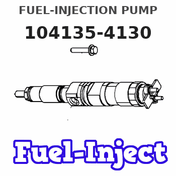
Information fuel-injection pump
BOSCH
F 01G 09Y 02U
f01g09y02u
ZEXEL
104135-4130
1041354130
ISHIKAWAJIMA-S
131011120
131011120
Rating:
Compare Prices: .
As an associate, we earn commssions on qualifying purchases through the links below

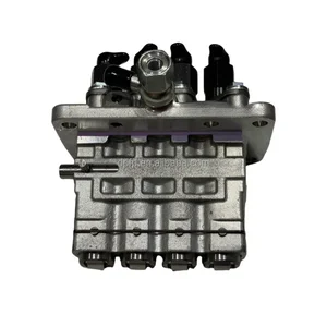
131011120 SBA131011120 104135-4130 Fuel Injection Pump for New Holland L160 L170 L175 L215 L218 L220 Tractor Boomer TT45A T2330 TT50A T2320 3050 3040 3045 4060 Loader
HIRINTOL 🔸Replace Part Number: 131011120 SBA131011120 104135-4130 || 🔸Engine Model: for Shibaura Engine ISM N844 || 🔸Compatible Model: for New Holland Tractor Boomer 8N, TT45A, Boomer 3050, Boomer 3040, T2330, TT50A, T2310, Boomer 3045, T2320, Workmaster 55, T2410, T2420, Boomer 4055, Boomer 4060, Workmaster 45, Boomer 50D, Boomer 45D, T1530 || 🔸Compatible Model: for New Holland Loader L213, C175, L160, L170, L175, L215, L218, L220 || 🔸Durable And Reliable: Tested and proven many times, it has a long life and reliable quality to keep working under extreme conditions.
HIRINTOL 🔸Replace Part Number: 131011120 SBA131011120 104135-4130 || 🔸Engine Model: for Shibaura Engine ISM N844 || 🔸Compatible Model: for New Holland Tractor Boomer 8N, TT45A, Boomer 3050, Boomer 3040, T2330, TT50A, T2310, Boomer 3045, T2320, Workmaster 55, T2410, T2420, Boomer 4055, Boomer 4060, Workmaster 45, Boomer 50D, Boomer 45D, T1530 || 🔸Compatible Model: for New Holland Loader L213, C175, L160, L170, L175, L215, L218, L220 || 🔸Durable And Reliable: Tested and proven many times, it has a long life and reliable quality to keep working under extreme conditions.

Fuel Injection Pump 131011120 131011011 for Perkins Engine 404D-22 404F-22
100% Apollo part number:131011120 131011011 || application: for Perkins Engine 404D-22 404F-22
100% Apollo part number:131011120 131011011 || application: for Perkins Engine 404D-22 404F-22

131011120 131011011 104135-4130 104135-4100 Fuel Injection Pump for Perkins 404D-22 404F-22 Engine
HIRINTOL 🔸Replace Part Number: 131011120, 131011011, 104135-4130, 104135-4100 || 🔸Engine Model: for Perkins 404D-22 404F-22 Engine || 🔸High-Standard Production: Precision-controlled fuel injectors, OE specification production, high quality raw materials, high standard production, excellent performance, perfect fit. || 🔸Durable Material: Manufactured with premium, long-lasting materials to meet original factory standards and undergo strict quality control, strong and durable, long service life. || 🔸Perfect Replaces: Pre-tested by the factory, this fuel injector is an easy-to-install replacement part that perfectly matches the original, come with free injector connecting tubes and offer a six-month-waranty.
HIRINTOL 🔸Replace Part Number: 131011120, 131011011, 104135-4130, 104135-4100 || 🔸Engine Model: for Perkins 404D-22 404F-22 Engine || 🔸High-Standard Production: Precision-controlled fuel injectors, OE specification production, high quality raw materials, high standard production, excellent performance, perfect fit. || 🔸Durable Material: Manufactured with premium, long-lasting materials to meet original factory standards and undergo strict quality control, strong and durable, long service life. || 🔸Perfect Replaces: Pre-tested by the factory, this fuel injector is an easy-to-install replacement part that perfectly matches the original, come with free injector connecting tubes and offer a six-month-waranty.
You can express buy:
USD 5083.35
19-05-2025
19-05-2025
104135-4130 1041354130 02634917 131011120 FPB1086RF Pump For Perkins Engine 404C 404D
Include in #1:
106673-7820
as _
Cross reference number
Zexel num
Bosch num
Firm num
Name
Information:
start by: a) remove pistons1. Remove the coolant from the cylinder block.2. Put covers on journals of crankshaft for protection from dirt or water. 3. Remove cylinder liners (1) with tooling (A).Install Cylinder Liners
1. Clean the cylinder liners (3) and the liner bores in the cylinder block.2. Install the cylinder liners in the block without the O-ring seals or filler bands.3. Check the cylinder liner projection as follows: a) Install the S1589 Bolts (2) and 1S379 Washers of tooling (B) on the cylinder block next to each liner. Tighten the bolts evenly, in four steps: 10 lb. ft. (14 N m), 25 lb. ft. (35 N m), 50 lb. ft. (70 N m) and 70 lb. ft. (95 N m).b) Put adapter plate on top of the liner and install the remainder of tooling (B). Tighten the 1D4595 Bolts (1) evenly in four steps: 5 lb. ft. (7 N m), 15 lb. ft. (20 N m), 25 lb. ft. (35 N m) and 50 lb. ft. (70 N m).c) Check to be sure the distance from the bottom edge of the crossbar to the top of the cylinder block is the same on both sides of the liner.d) Check the cylinder liner projection with tool group (C) at four locations around the liner.e) Liner projection must be .0013 to .0069 in. (0.033 to 0.175 mm). Measurements on the same liner must not be different by more than .002 in. (0.05 mm). Average measurements between liners next to each other must not be different by more than .002 in. (0.05 mm). The maximum permissible difference between average projection of all cylinder liners under one cylinder head is .004 in. (0.10 mm). If the liner is turned in the bore, it can make a difference in the liner projection.4. If the liner projection is not .0013 to .0069 in. (0.033 to 0.175 mm), check the thickness of the following parts: spacer plate, spacer plate gasket and cylinder liner flange. The thickness of the spacer plate must be .3925 .0010 in. (9.970 0.025 mm). The thickness of the spacer plate gasket must be .0082 .0010 in. (0.208 0.025 mm). The thickness of the cylinder liner flange must be .4048 .0008 in. (10.282 0.020 mm). If the liner projection changes from point to point around the liner, turn the liner to a new position in the bore. If the liner projection is still not to specifications, move the liner to a different bore.5. When the cylinder projection is correct, put a mark on the liner and block so the liner can be installed in the same position from which it was removed. Cylinder liner projection can be adjusted by the removal of material from (machining) the contact face of the cylinder block with
1. Clean the cylinder liners (3) and the liner bores in the cylinder block.2. Install the cylinder liners in the block without the O-ring seals or filler bands.3. Check the cylinder liner projection as follows: a) Install the S1589 Bolts (2) and 1S379 Washers of tooling (B) on the cylinder block next to each liner. Tighten the bolts evenly, in four steps: 10 lb. ft. (14 N m), 25 lb. ft. (35 N m), 50 lb. ft. (70 N m) and 70 lb. ft. (95 N m).b) Put adapter plate on top of the liner and install the remainder of tooling (B). Tighten the 1D4595 Bolts (1) evenly in four steps: 5 lb. ft. (7 N m), 15 lb. ft. (20 N m), 25 lb. ft. (35 N m) and 50 lb. ft. (70 N m).c) Check to be sure the distance from the bottom edge of the crossbar to the top of the cylinder block is the same on both sides of the liner.d) Check the cylinder liner projection with tool group (C) at four locations around the liner.e) Liner projection must be .0013 to .0069 in. (0.033 to 0.175 mm). Measurements on the same liner must not be different by more than .002 in. (0.05 mm). Average measurements between liners next to each other must not be different by more than .002 in. (0.05 mm). The maximum permissible difference between average projection of all cylinder liners under one cylinder head is .004 in. (0.10 mm). If the liner is turned in the bore, it can make a difference in the liner projection.4. If the liner projection is not .0013 to .0069 in. (0.033 to 0.175 mm), check the thickness of the following parts: spacer plate, spacer plate gasket and cylinder liner flange. The thickness of the spacer plate must be .3925 .0010 in. (9.970 0.025 mm). The thickness of the spacer plate gasket must be .0082 .0010 in. (0.208 0.025 mm). The thickness of the cylinder liner flange must be .4048 .0008 in. (10.282 0.020 mm). If the liner projection changes from point to point around the liner, turn the liner to a new position in the bore. If the liner projection is still not to specifications, move the liner to a different bore.5. When the cylinder projection is correct, put a mark on the liner and block so the liner can be installed in the same position from which it was removed. Cylinder liner projection can be adjusted by the removal of material from (machining) the contact face of the cylinder block with