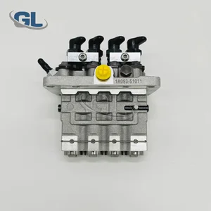
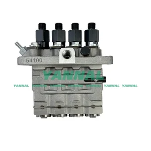
Information fuel-injection pump
ZEXEL
104135-4100
1041354100
ISHIKAWAJIMA-S
131011100
131011100

Rating:
Compare Prices: .
As an associate, we earn commssions on qualifying purchases through the links below

Zuide 1041354100 Fuel Injection Pump Compatible with Zexel
Zuide Part Name: Fuel Injection Pump || Part number: 104135-4100 1041354100 || Application: Compatible with Zexel || Professional installation is highly recommended. || please ask to us if you have any questions with this item
Zuide Part Name: Fuel Injection Pump || Part number: 104135-4100 1041354100 || Application: Compatible with Zexel || Professional installation is highly recommended. || please ask to us if you have any questions with this item

1041354100 104135-4100 Fuel Injection Pump Compatible with Zexel
ZHLQUAMYTH Part Name:Fuel Injection Pump || Part Number:1041354100 104135-4100 || Application:Compatible with Zexel || Friendly tips:This product boasts excellent performance, superior quality, reliability and safety. It is your reliable choice. || Your choice holds great significance for us. Not only do we sell products, but we also strive to provide "safety and performance assurance" for your beloved car. Your satisfaction is our eternal pursuit.We will offer the most sincere service.
ZHLQUAMYTH Part Name:Fuel Injection Pump || Part Number:1041354100 104135-4100 || Application:Compatible with Zexel || Friendly tips:This product boasts excellent performance, superior quality, reliability and safety. It is your reliable choice. || Your choice holds great significance for us. Not only do we sell products, but we also strive to provide "safety and performance assurance" for your beloved car. Your satisfaction is our eternal pursuit.We will offer the most sincere service.

IMIFAFTAbT 104135-4100 1041354100 Fuel injection pump Fits for Zexel for Perkins Engine for Caterpillar 3024C C2.2 Engine
IMIFAFTAbT Product Name: 104135-4100 1041354100 Fuel injection pump || Part number: 104135-4100 1041354100 || Fits for Zexel for Perkins Engine for Caterpillar 3024C C2.2 Engine || 1 PCS Fuel injection pump || Note: Please confirm that the product shown in the part number is what you need. If you cannot confirm you can leave us a message and provide your engine serial number and nameplate
IMIFAFTAbT Product Name: 104135-4100 1041354100 Fuel injection pump || Part number: 104135-4100 1041354100 || Fits for Zexel for Perkins Engine for Caterpillar 3024C C2.2 Engine || 1 PCS Fuel injection pump || Note: Please confirm that the product shown in the part number is what you need. If you cannot confirm you can leave us a message and provide your engine serial number and nameplate
You can express buy:
USD 392.84
27-06-2025
27-06-2025
China Made New Fuel Injection Pump Head 131011100 104135-4100 Fits for Perkins
USD 636.33
23-05-2025
23-05-2025
For Perkins 404D-22T Fuel Injection Pump 131011100 104135-4100 Excavator Parts
Images:
USD 636.33

[23-May-2025]
USD 478.15

[01-Jul-2025]
USD 1744.57

[19-May-2025]
Components :
| 0. | INJECTION-PUMP ASSEMBLY | 104135-4100 |
| 1. | _ | |
| 2. | FUEL INJECTION PUMP | |
| 3. | NUMBER PLATE | |
| 4. | _ | |
| 5. | CAPSULE | |
| 6. | ADJUSTING DEVICE | |
| 7. | NOZZLE AND HOLDER ASSY | |
| 8. | Nozzle and Holder | |
| 9. | Open Pre:MPa(Kqf/cm2) | |
| 10. | NOZZLE-HOLDER | |
| 11. | NOZZLE |
Scheme ###:
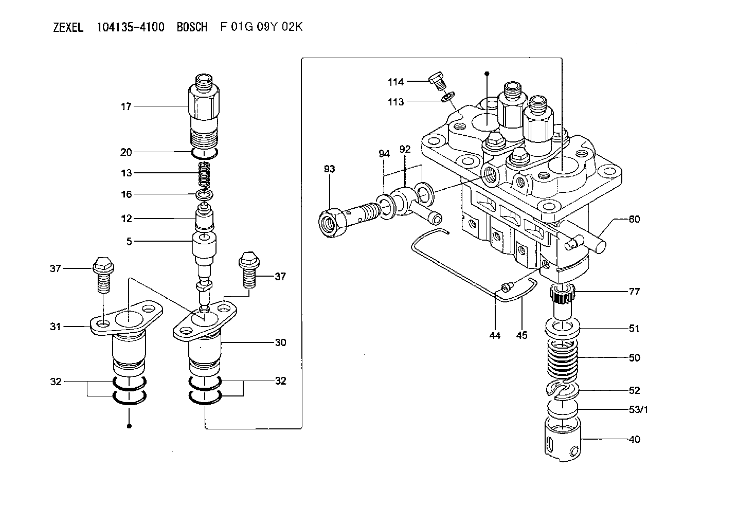
| 5. | [4] | 140163-5021 | PLUNGER-AND-BARREL ASSY K342 |
| 12. | [4] | 140110-3620 | DELIVERY-VALVE ASSEMBLY K15 |
| 13. | [4] | 140112-2900 | COMPRESSION SPRING |
| 16. | [4] | 140115-1400 | GASKET |
| 17. | [4] | 140116-7520 | FITTING |
| 20. | [4] | 140118-0301 | O-RING |
| 30. | [3] | 140131-0521 | FLANGE BUSHING |
| 31. | [1] | 140131-1021 | FLANGE BUSHING |
| 32. | [8] | 140118-0201 | O-RING |
| 32. | [8] | 140118-0201 | O-RING |
| 37. | [8] | 140124-0200 | BLEEDER SCREW |
| 37. | [8] | 140124-0200 | BLEEDER SCREW |
| 40. | [4] | 140200-2620 | TAPPET |
| 44. | [4] | 140212-0300 | BEARING PIN |
| 45. | [1] | 140213-1500 | LOCKING WASHER |
| 50. | [4] | 140215-1900 | COMPRESSION SPRING |
| 51. | [4] | 140216-0800 | SLOTTED WASHER |
| 52. | [4] | 140217-2200 | SLOTTED WASHER |
| 53/1. | [1] | 140217-5000 | PLATE D19T2.60 |
| 53/1. | [1] | 140217-5100 | PLATE D19T2.65 |
| 53/1. | [1] | 140217-5200 | PLATE D19T2.70 |
| 53/1. | [1] | 140217-5300 | PLATE D19T2.75 |
| 53/1. | [1] | 140217-5400 | PLATE D19T2.80 |
| 53/1. | [1] | 140217-5500 | PLATE D19T2.85 |
| 53/1. | [1] | 140217-5600 | PLATE D19T2.90 |
| 53/1. | [1] | 140217-5700 | PLATE D19T2.95 |
| 53/1. | [1] | 140217-5800 | PLATE D19T3.00 |
| 53/1. | [1] | 140217-5900 | PLATE D19T3.05 |
| 53/1. | [1] | 140217-6000 | PLATE D19T3.10 |
| 53/1. | [1] | 140217-6100 | PLATE D19T3.15 |
| 53/1. | [1] | 140217-6200 | PLATE D19T3.20 |
| 53/1. | [1] | 140217-6300 | PLATE D19T3.25 |
| 53/1. | [1] | 140217-6400 | PLATE D19T3.30 |
| 53/1. | [1] | 140217-6500 | PLATE D19T3.35 |
| 53/1. | [1] | 140217-6600 | PLATE D19T3.40 |
| 53/1. | [1] | 140217-6700 | PLATE D19T3.45 |
| 53/1. | [1] | 140217-6800 | PLATE D19T3.50 |
| 53/1. | [1] | 140217-6900 | PLATE D19T3.55 |
| 53/1. | [1] | 140217-7000 | PLATE D19T3.60 |
| 53/1. | [1] | 140217-7100 | PLATE D19T3.65 |
| 53/1. | [1] | 140217-7200 | PLATE D19T3.70 |
| 53/1. | [1] | 140217-7300 | PLATE D19T3.75 |
| 53/1. | [1] | 140217-7400 | PLATE D19T3.80 |
| 53/1. | [1] | 140217-7500 | PLATE D19T3.85 |
| 53/1. | [1] | 140217-7600 | PLATE D19T3.90 |
| 53/1. | [1] | 140217-7700 | PLATE D19T3.95 |
| 53/1. | [1] | 140217-7800 | PLATE D19T4.00 |
| 53/1. | [1] | 140217-7900 | PLATE D19T4.05 |
| 53/1. | [1] | 140217-8000 | PLATE D19T4.10 |
| 53/1. | [1] | 140253-2000 | PLATE D19T2.625 |
| 53/1. | [1] | 140253-2100 | PLATE D19T2.675 |
| 53/1. | [1] | 140253-2200 | PLATE D19T2.725 |
| 53/1. | [1] | 140253-2300 | PLATE D19T2.775 |
| 53/1. | [1] | 140253-2400 | PLATE D19T2.825 |
| 53/1. | [1] | 140253-2500 | PLATE D19T2.875 |
| 53/1. | [1] | 140253-2600 | PLATE D19T2.925 |
| 53/1. | [1] | 140253-2700 | PLATE D19T2.975 |
| 53/1. | [1] | 140253-2800 | PLATE D19T3.025 |
| 53/1. | [1] | 140253-2900 | PLATE D19T3.075 |
| 53/1. | [1] | 140253-3000 | PLATE D19T3.125 |
| 53/1. | [1] | 140253-3100 | PLATE D19T3.175 |
| 53/1. | [1] | 140253-3200 | PLATE D19T3.225 |
| 53/1. | [1] | 140253-3300 | PLATE D19T3.275 |
| 53/1. | [1] | 140253-3400 | PLATE D19T3.325 |
| 53/1. | [1] | 140253-3500 | PLATE D19T3.375 |
| 53/1. | [1] | 140253-3600 | PLATE D19T3.425 |
| 53/1. | [1] | 140253-3700 | PLATE D19T3.475 |
| 53/1. | [1] | 140253-3800 | PLATE D19T3.525 |
| 53/1. | [1] | 140253-3900 | PLATE D19T3.575 |
| 53/1. | [1] | 140253-4000 | PLATE D19T3.625 |
| 53/1. | [1] | 140253-4100 | PLATE D19T3.675 |
| 53/1. | [1] | 140253-4200 | PLATE D19T3.725 |
| 53/1. | [1] | 140253-4300 | PLATE D19T3.775 |
| 53/1. | [1] | 140253-4400 | PLATE D19T3.825 |
| 53/1. | [1] | 140253-4500 | PLATE D19T3.875 |
| 53/1. | [1] | 140253-4600 | PLATE D19T3.925 |
| 53/1. | [1] | 140253-4700 | PLATE D19T3.975 |
| 53/1. | [1] | 140253-4800 | PLATE D19T4.025 |
| 53/1. | [1] | 140253-4900 | PLATE D19T4.075 |
| 60. | [1] | 140243-8020 | CONTROL RACK |
| 77. | [4] | 140241-2700 | CONTROL SLEEVE |
| 92. | [1] | 029711-2050 | INLET UNION |
| 93. | [1] | 140402-1300 | EYE BOLT |
| 94. | [2] | 026512-1540 | GASKET |
| 113. | [1] | 026508-1240 | GASKET D11.9&8.2T1.0 |
| 114. | [1] | 140420-1400 | BLEEDER SCREW |
Include in #1:
106673-7790
as _
Include in #2:
104135-4100
as INJECTION-PUMP ASSEMBLY
Cross reference number
Zexel num
Bosch num
Firm num
Name
Information:
start by:a) remove pistons1. Check to be sure that all coolant has been removed from the cylinder block.2. Put a cover over the crankshaft journals before liners are removed. 3. Install tool (A) and remove the cylinder liners. 4. Remove filler band (1) and O-ring seals (2) from the cylinder liners.Install Cylinder Liners
1. Clean the cylinder liners and cylinder block. 2. Install the liners (1) in the cylinder block without the O-ring seals and filler bands. See CYLINDER LINER PROJECTION in TESTING AND ADJUSTING. 3. Install tooling (A) and two 5/8" - 11 NC bolts 5 1/2 in. long. Tighten the bolts evenly to 50 lb.ft. (70 N m).4. Check the liner projection with tool (B) at four locations around the liner.5. Liner projection must be .0020 to .0056 in. (0.051 to 0.142 mm). Measurements on the same liner must not be different by more than .002 in. (0.05 mm). Average measurement between liners next to each other must not be different by more than .002 in. (0.05 mm). The maximum permissible difference between average projection of all cylinder liners under one cylinder head is .004 in. (0.10 mm). The liner projection can change if the liner is turned in the bore. 6. If the liner projection is not .0020 to .0056 in. (0.051 to 0.142 mm), check the thickness of the liner flange (2) and the depth of the liner bore in the cylinder block. The thickness of the liner flange (2) must be .4048 .0008 in. (10.282 0.020 mm).7. The depth of the liner bore in the cylinder block must be .401 .001 in. (10.19 0.03 mm). If the liner bore in the block is worn and the measurement is not correct, the liner bore can be corrected with a cylinder block counterboring tool. See SPECIAL INSTRUCTIONS, FORM FM055228.8. Put a mark on the liner and cylinder block so the liner can be installed in the same position from which it was removed. 9. Install new O-ring seals (4) on the cylinder liners. Put liquid soap on the O-ring seals and in the bases in the cylinder block.
The liners must be installed in the cylinder block immediately after filler band (3) is installed. Make sure the marks on the liners and the cylinder block are in alignment when the cylinder liners are installed.
10. Put (dip) the filler band completely in clean SAE 30 oil and install it on the liner immediately.11. Install the liner in the cylinder block immediately with tooling (C).end by:a) install pistons