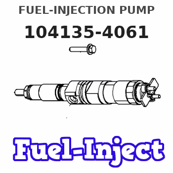
Information fuel-injection pump
BOSCH
9 410 618 469
9410618469
ZEXEL
104135-4061
1041354061
ISHIKAWAJIMA-S
131010031
131010031
Rating:
Compare Prices: .
As an associate, we earn commssions on qualifying purchases through the links below

Fuel Injection Pump 131010031 for Perkins Engine 404D-22 404D-22T 404C-22 404C-22T 404D-22TA
FGNTWP Part Number:131010031, 104135-4060, 104135-4061, 1041354060, 1041354061 || Applications:for Perkins Engine 404D-22 404D-22T 404C-22 404C-22T 404D-22TA
FGNTWP Part Number:131010031, 104135-4060, 104135-4061, 1041354060, 1041354061 || Applications:for Perkins Engine 404D-22 404D-22T 404C-22 404C-22T 404D-22TA

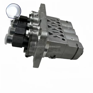
Fuel Injection Pump 9410618469 XYohykai Fits for 844 Engine for Holland Tractor 3415 TC48DA TC55DA
XYohykai ◆Part Name◆:Fuel Injection Pump || ◆Part Number◆:9410618469 || ◆Application◆: XYohykai Fits for 844 Engine XYohykai Fits for Holland Tractor 3415 TC48DA TC55DA || ◆Notice◆-Application information provided is for reference only. Please confirm the part number and compare old parts before purchase. If you have any question pls feel free to ask us. || ◆Worth Choice◆-This product has stable performance high reliability easy installation and fast response.
XYohykai ◆Part Name◆:Fuel Injection Pump || ◆Part Number◆:9410618469 || ◆Application◆: XYohykai Fits for 844 Engine XYohykai Fits for Holland Tractor 3415 TC48DA TC55DA || ◆Notice◆-Application information provided is for reference only. Please confirm the part number and compare old parts before purchase. If you have any question pls feel free to ask us. || ◆Worth Choice◆-This product has stable performance high reliability easy installation and fast response.

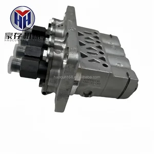
Fuel Injection Pump 9410618469 Compatible with 844 Engine for Holland Tractor 3415 TC48DA TC55DA
DJCXYSM Product Name:Fuel Injection Pump || Part Number:9410618469 || Application: Compatible with 844 Engine Compatible with Holland Tractor 3415 TC48DA TC55DA || NOTE: To avoid unnecessary returns DJCXYSM please check the part number before purchasing or tell us the picture of your engine model and nameplate to reduce the error rate. || Tip: Please purchase according to the part number, as there may be discrepancies between the pictures and the actual product.
DJCXYSM Product Name:Fuel Injection Pump || Part Number:9410618469 || Application: Compatible with 844 Engine Compatible with Holland Tractor 3415 TC48DA TC55DA || NOTE: To avoid unnecessary returns DJCXYSM please check the part number before purchasing or tell us the picture of your engine model and nameplate to reduce the error rate. || Tip: Please purchase according to the part number, as there may be discrepancies between the pictures and the actual product.
You can express buy:
USD 652.97
14-06-2025
14-06-2025
Perkins 404D-22 404C-22 Engine 131010031 131010080 Fuel Pump Construction Machinery Excavators Hydraulic Piston
USD 650.69
14-06-2025
14-06-2025
Perkins 404D-22 404C-22 Engine 131010031 131010080 Fuel Pump Construction Machinery Excavators Hydraulic Piston
USD 481.19
14-06-2025
14-06-2025
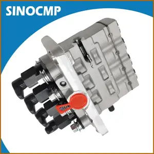
Excavator Fuel Pump 131010031 104135-4061 9410618469 For Kubota Perkins 404D-22 404D-22T 404D-22TA 404C-22 404C-22T Engine
Images:
USD 481.19

[14-Jun-2025]
USD 840.81

[14-Jun-2025]
USD 393.12

[01-Jul-2025]
Components :
| 0. | INJECTION-PUMP ASSEMBLY | 104135-4061 |
| 1. | _ | |
| 2. | FUEL INJECTION PUMP | |
| 3. | NUMBER PLATE | |
| 4. | _ | |
| 5. | CAPSULE | |
| 6. | ADJUSTING DEVICE | |
| 7. | NOZZLE AND HOLDER ASSY | 105148-1170 |
| 8. | Nozzle and Holder | |
| 9. | Open Pre:MPa(Kqf/cm2) | 14.7(150) |
| 10. | NOZZLE-HOLDER | 105078-0100 |
| 11. | NOZZLE | 105007-1170 |
Scheme ###:
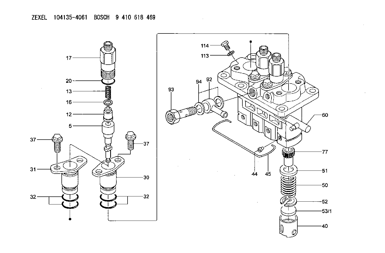
| 5. | [4] | 140163-2020 | PLUNGER-AND-BARREL ASSY |
| 12. | [4] | 140110-3620 | DELIVERY-VALVE ASSEMBLY |
| 13. | [4] | 140112-2900 | COMPRESSION SPRING |
| 16. | [4] | 140115-1400 | GASKET |
| 17. | [4] | 140116-7520 | FITTING |
| 20. | [4] | 140118-0301 | O-RING |
| 30. | [3] | 140131-0521 | FLANGE BUSHING |
| 31. | [1] | 140131-1021 | FLANGE BUSHING |
| 32. | [8] | 140118-0201 | O-RING |
| 32. | [8] | 140118-0201 | O-RING |
| 37. | [8] | 140124-0200 | BLEEDER SCREW |
| 37. | [8] | 140124-0200 | BLEEDER SCREW |
| 40. | [4] | 140200-2620 | TAPPET |
| 44. | [4] | 140212-0300 | BEARING PIN |
| 45. | [1] | 140213-1500 | LOCKING WASHER |
| 50. | [4] | 140215-1900 | COMPRESSION SPRING |
| 51. | [4] | 140216-0800 | SLOTTED WASHER |
| 52. | [4] | 140217-2200 | SLOTTED WASHER |
| 53/1. | [1] | 140217-5000 | PLATE D19T2.60 |
| 53/1. | [1] | 140217-5100 | PLATE D19T2.65 |
| 53/1. | [1] | 140217-5200 | PLATE D19T2.70 |
| 53/1. | [1] | 140217-5300 | PLATE D19T2.75 |
| 53/1. | [1] | 140217-5400 | PLATE D19T2.80 |
| 53/1. | [1] | 140217-5500 | PLATE D19T2.85 |
| 53/1. | [1] | 140217-5600 | PLATE D19T2.90 |
| 53/1. | [1] | 140217-5700 | PLATE D19T2.95 |
| 53/1. | [1] | 140217-5800 | PLATE D19T3.00 |
| 53/1. | [1] | 140217-5900 | PLATE D19T3.05 |
| 53/1. | [1] | 140217-6000 | PLATE D19T3.10 |
| 53/1. | [1] | 140217-6100 | PLATE D19T3.15 |
| 53/1. | [1] | 140217-6200 | PLATE D19T3.20 |
| 53/1. | [1] | 140217-6300 | PLATE D19T3.25 |
| 53/1. | [1] | 140217-6400 | PLATE D19T3.30 |
| 53/1. | [1] | 140217-6500 | PLATE D19T3.35 |
| 53/1. | [1] | 140217-6600 | PLATE D19T3.40 |
| 53/1. | [1] | 140217-6700 | PLATE D19T3.45 |
| 53/1. | [1] | 140217-6800 | PLATE D19T3.50 |
| 53/1. | [1] | 140217-6900 | PLATE D19T3.55 |
| 53/1. | [1] | 140217-7000 | PLATE D19T3.60 |
| 53/1. | [1] | 140217-7100 | PLATE D19T3.65 |
| 53/1. | [1] | 140217-7200 | PLATE D19T3.70 |
| 53/1. | [1] | 140217-7300 | PLATE D19T3.75 |
| 53/1. | [1] | 140217-7400 | PLATE D19T3.80 |
| 53/1. | [1] | 140217-7500 | PLATE D19T3.85 |
| 53/1. | [1] | 140217-7600 | PLATE D19T3.90 |
| 53/1. | [1] | 140217-7700 | PLATE D19T3.95 |
| 53/1. | [1] | 140217-7800 | PLATE D19T4.00 |
| 53/1. | [1] | 140217-7900 | PLATE D19T4.05 |
| 53/1. | [1] | 140217-8000 | PLATE D19T4.10 |
| 53/1. | [1] | 140253-2000 | PLATE |
| 53/1. | [1] | 140253-2100 | PLATE |
| 53/1. | [1] | 140253-2200 | PLATE |
| 53/1. | [1] | 140253-2300 | PLATE |
| 53/1. | [1] | 140253-2400 | PLATE |
| 53/1. | [1] | 140253-2500 | PLATE |
| 53/1. | [1] | 140253-2600 | PLATE |
| 53/1. | [1] | 140253-2700 | PLATE |
| 53/1. | [1] | 140253-2800 | PLATE |
| 53/1. | [1] | 140253-2900 | PLATE |
| 53/1. | [1] | 140253-3000 | PLATE |
| 53/1. | [1] | 140253-3100 | PLATE |
| 53/1. | [1] | 140253-3200 | PLATE |
| 53/1. | [1] | 140253-3300 | PLATE |
| 53/1. | [1] | 140253-3400 | PLATE |
| 53/1. | [1] | 140253-3500 | PLATE |
| 53/1. | [1] | 140253-3600 | PLATE |
| 53/1. | [1] | 140253-3700 | PLATE |
| 53/1. | [1] | 140253-3800 | PLATE |
| 53/1. | [1] | 140253-3900 | PLATE |
| 53/1. | [1] | 140253-4000 | PLATE |
| 53/1. | [1] | 140253-4100 | PLATE |
| 53/1. | [1] | 140253-4200 | PLATE |
| 53/1. | [1] | 140253-4300 | PLATE |
| 53/1. | [1] | 140253-4400 | PLATE |
| 53/1. | [1] | 140253-4500 | PLATE |
| 53/1. | [1] | 140253-4600 | PLATE |
| 53/1. | [1] | 140253-4700 | PLATE |
| 53/1. | [1] | 140253-4800 | PLATE |
| 53/1. | [1] | 140253-4900 | PLATE |
| 60. | [1] | 140243-8020 | CONTROL RACK |
| 77. | [4] | 140241-2700 | CONTROL SLEEVE |
| 92. | [1] | 029711-2050 | INLET UNION |
| 93. | [1] | 140402-1300 | EYE BOLT |
| 94. | [2] | 026512-1540 | GASKET D15.4&12.2T1.50 |
| 113. | [1] | 026508-1240 | GASKET D11.9&8.2T1 |
| 114. | [1] | 140420-1400 | BLEEDER SCREW |
Include in #2:
104135-4061
as INJECTION-PUMP ASSEMBLY
Cross reference number
Zexel num
Bosch num
Firm num
Name
Information:
start by:a) remove flywheel 1. Use tool (A) to remove the crankshaft rear seal.2. Install tool (C) in the rear seal bore.
TYPICAL EXAMPLE3. Install tool (B) between tool (C) and the wear sleeve. Turn tool (B) until the ends of the tool make a flat piece (crease) in the wear sleeve. Do this in two or more places until the wear sleeve is loose.4. Remove tool (C) and the wear sleeve by hand.Install Crankshaft Rear Seal And Wear Sleeve
1. Install the crankshaft rear seal and wear sleeve with tooling (A) as follows: a) Put locator (1) in position on the crankshaft and install the three bolts that hold it in place.b) Put clean engine oil on the seal lip of seal (6) and on the outside diameter of wear sleeve (2).c) Install seal (6) on wear sleeve (2) from the end of the wear sleeve that has the bevel on the outside diameter. Make sure the lip of the seal is toward the inside of the engine and the bevel that is on the outside diameter of the wear sleeve is toward the outside of the engine when installed.d) Use 8M8060 Quick Cure Primer to clean the outside diameter of the crankshaft flange (3) and the inside diameter of wear sleeve (2).e) Put 9S3265 Retaining Compound on the outside diameter of crankshaft flange (3) and the inside diameter of wear sleeve (2). Make sure the lip of the seal is toward the inside of the engine and the outside diameter bevel of the wear sleeve is toward the outside of the engine.f) Put wear sleeve (2) with seal (6) on locator (1). Put installer (4) on locator (1) and install nut (5). Put lubrication on the face of the washer and the nut.g) Tighten nut (5) until installer (4) comes in contact with locator (1).h) Remove tooling (A) and check the wear sleeve and seal for correct installation.end by:a) install flywheel