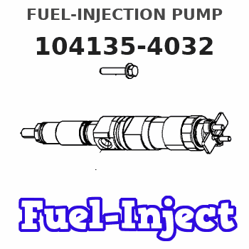
Information fuel-injection pump
BOSCH
9 410 618 468
9410618468
ZEXEL
104135-4032
1041354032
ISHIKAWAJIMA-S
131017801
131017801
Rating:
Compare Prices: .
As an associate, we earn commssions on qualifying purchases through the links below

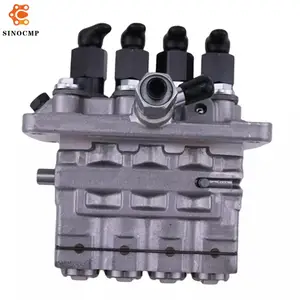
Fuel Injection Pump 131017630 131017801 for Perkins Engine 404D-22 404D-22T 404D-22TA 404C-22
DIGERTECH Part number:131017630 || Application: for Perkins Engine 404D-22 404D-22T 404D-22TA 404C-22
DIGERTECH Part number:131017630 || Application: for Perkins Engine 404D-22 404D-22T 404D-22TA 404C-22

Fuel Injection Pump 131017800 131017801 for Perkins Engine 404D-22 404C-22
FGNTWP Part Number:131017800, 131017801, 104135-4032, 1041354032, 104135-4030, 1041354030, 104135-4031, 1041354031 || Applications:for Perkins Engine 404D-22 404C-22
FGNTWP Part Number:131017800, 131017801, 104135-4032, 1041354032, 104135-4030, 1041354030, 104135-4031, 1041354031 || Applications:for Perkins Engine 404D-22 404C-22

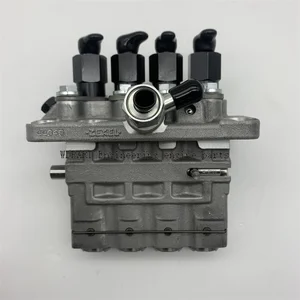
VIIKEND Fuel Injection Pump 131017800 131017801 104135-4031 Compatible with Perkins Engine 404D-22 404C-22 404D-22T 404D-22TA Compatible with New Holland C175 LS160
VIIKEND Part Name: Fuel Injection Pump || Part Number: 131017800 131017801 Note: Please check the fitment carefully before purchase. Or just tell us the part number you need. || Engine Model: 404D-22T || Applicable: Compatible with Perkins Engine 404D-22 404C-22 404D-22T 404D-22TA || Compatible with New Holland Skid Steer Loader L160 L170 L175 L218 C175 LS160 LS170 L215 Tractor TT45A TT50A
VIIKEND Part Name: Fuel Injection Pump || Part Number: 131017800 131017801 Note: Please check the fitment carefully before purchase. Or just tell us the part number you need. || Engine Model: 404D-22T || Applicable: Compatible with Perkins Engine 404D-22 404C-22 404D-22T 404D-22TA || Compatible with New Holland Skid Steer Loader L160 L170 L175 L218 C175 LS160 LS170 L215 Tractor TT45A TT50A
You can express buy:
USD 587.72
14-06-2025
14-06-2025
Fuel Injection Pump 104135-4032 131017801 For Bocsh Perkins 404D CAT 216B 232B Fuel Supply System Accessories
USD 1047.75
19-05-2025
19-05-2025
Fuel Injection Pump 131010080 for Perkins 404D-22 404C-22 104-19 308-1905 10000-06101 10000-05837 104134-4060 104135-4032
Images:
USD 637.44

[14-Jun-2025]
USD 393.12

[01-Jul-2025]
Components :
| 0. | INJECTION-PUMP ASSEMBLY | 104135-4032 |
| 1. | _ | |
| 2. | FUEL INJECTION PUMP | |
| 3. | NUMBER PLATE | |
| 4. | _ | |
| 5. | CAPSULE | |
| 6. | ADJUSTING DEVICE | |
| 7. | NOZZLE AND HOLDER ASSY | 105148-1170 |
| 8. | Nozzle and Holder | |
| 9. | Open Pre:MPa(Kqf/cm2) | 14.7(150) |
| 10. | NOZZLE-HOLDER | 105078-0100 |
| 11. | NOZZLE | 105007-1170 |
Scheme ###:
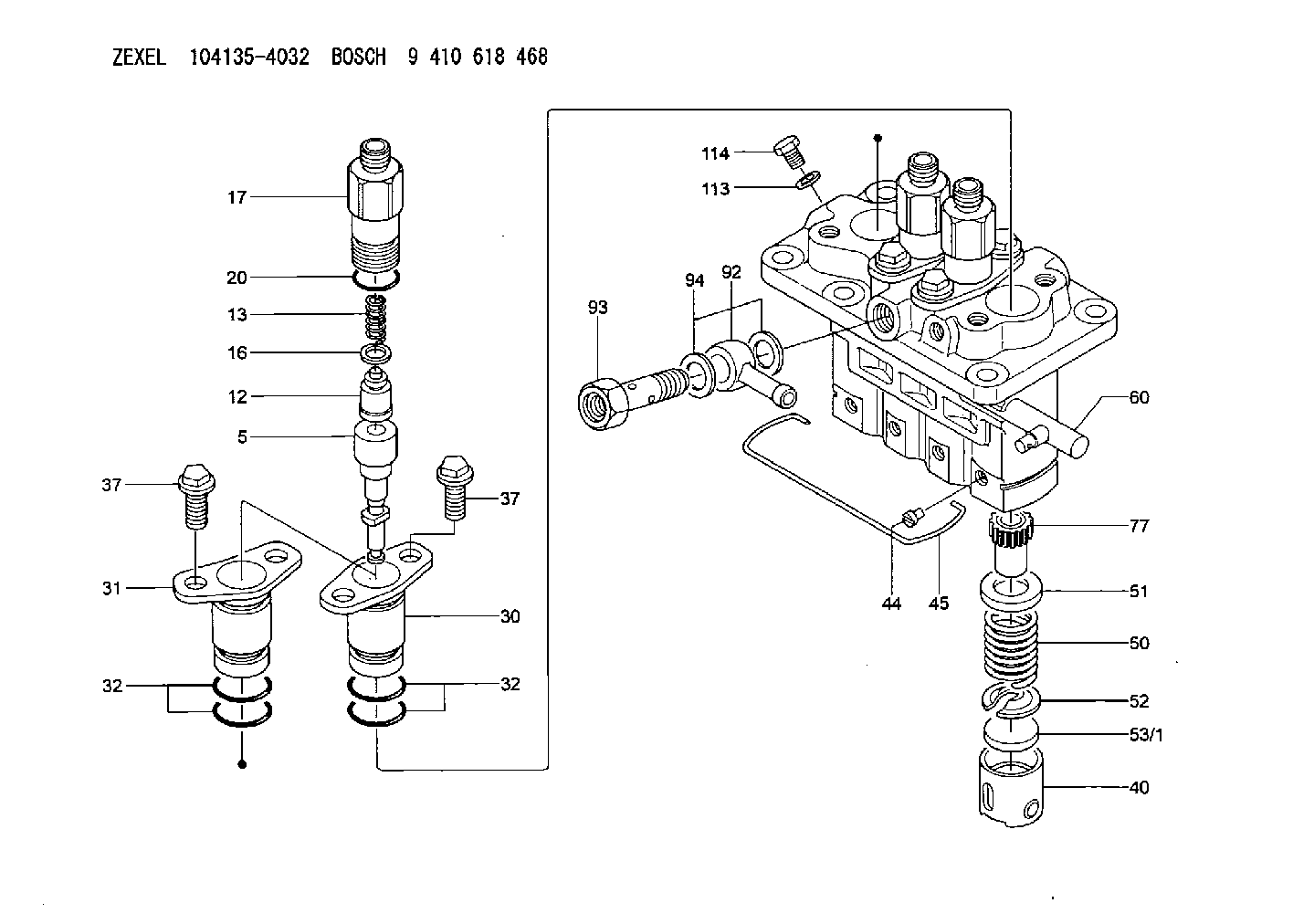
| 5. | [4] | 140163-2020 | PLUNGER-AND-BARREL ASSY |
| 12. | [4] | 140110-3620 | DELIVERY-VALVE ASSEMBLY |
| 13. | [4] | 140112-2900 | COMPRESSION SPRING |
| 16. | [4] | 140115-1400 | GASKET |
| 17. | [4] | 140116-7520 | FITTING |
| 20. | [4] | 140118-0301 | O-RING |
| 30. | [3] | 140131-0521 | FLANGE BUSHING |
| 31. | [1] | 140131-1021 | FLANGE BUSHING |
| 32. | [8] | 140118-0201 | O-RING |
| 32. | [8] | 140118-0201 | O-RING |
| 37. | [8] | 140124-0200 | BLEEDER SCREW |
| 37. | [8] | 140124-0200 | BLEEDER SCREW |
| 40. | [4] | 140200-2620 | TAPPET |
| 44. | [4] | 140212-0300 | BEARING PIN |
| 45. | [1] | 140213-1500 | LOCKING WASHER |
| 50. | [4] | 140215-1900 | COMPRESSION SPRING |
| 51. | [4] | 140216-0800 | SLOTTED WASHER |
| 52. | [4] | 140217-2200 | SLOTTED WASHER |
| 53/1. | [1] | 140217-5000 | PLATE D19T2.60 |
| 53/1. | [1] | 140217-5100 | PLATE D19T2.65 |
| 53/1. | [1] | 140217-5200 | PLATE D19T2.70 |
| 53/1. | [1] | 140217-5300 | PLATE D19T2.75 |
| 53/1. | [1] | 140217-5400 | PLATE D19T2.80 |
| 53/1. | [1] | 140217-5500 | PLATE D19T2.85 |
| 53/1. | [1] | 140217-5600 | PLATE D19T2.90 |
| 53/1. | [1] | 140217-5700 | PLATE D19T2.95 |
| 53/1. | [1] | 140217-5800 | PLATE D19T3.00 |
| 53/1. | [1] | 140217-5900 | PLATE D19T3.05 |
| 53/1. | [1] | 140217-6000 | PLATE D19T3.10 |
| 53/1. | [1] | 140217-6100 | PLATE D19T3.15 |
| 53/1. | [1] | 140217-6200 | PLATE D19T3.20 |
| 53/1. | [1] | 140217-6300 | PLATE D19T3.25 |
| 53/1. | [1] | 140217-6400 | PLATE D19T3.30 |
| 53/1. | [1] | 140217-6500 | PLATE D19T3.35 |
| 53/1. | [1] | 140217-6600 | PLATE D19T3.40 |
| 53/1. | [1] | 140217-6700 | PLATE D19T3.45 |
| 53/1. | [1] | 140217-6800 | PLATE D19T3.50 |
| 53/1. | [1] | 140217-6900 | PLATE D19T3.55 |
| 53/1. | [1] | 140217-7000 | PLATE D19T3.60 |
| 53/1. | [1] | 140217-7100 | PLATE D19T3.65 |
| 53/1. | [1] | 140217-7200 | PLATE D19T3.70 |
| 53/1. | [1] | 140217-7300 | PLATE D19T3.75 |
| 53/1. | [1] | 140217-7400 | PLATE D19T3.80 |
| 53/1. | [1] | 140217-7500 | PLATE D19T3.85 |
| 53/1. | [1] | 140217-7600 | PLATE D19T3.90 |
| 53/1. | [1] | 140217-7700 | PLATE D19T3.95 |
| 53/1. | [1] | 140217-7800 | PLATE D19T4.00 |
| 53/1. | [1] | 140217-7900 | PLATE D19T4.05 |
| 53/1. | [1] | 140217-8000 | PLATE D19T4.10 |
| 53/1. | [1] | 140253-2000 | PLATE |
| 53/1. | [1] | 140253-2100 | PLATE |
| 53/1. | [1] | 140253-2200 | PLATE |
| 53/1. | [1] | 140253-2300 | PLATE |
| 53/1. | [1] | 140253-2400 | PLATE |
| 53/1. | [1] | 140253-2500 | PLATE |
| 53/1. | [1] | 140253-2600 | PLATE |
| 53/1. | [1] | 140253-2700 | PLATE |
| 53/1. | [1] | 140253-2800 | PLATE |
| 53/1. | [1] | 140253-2900 | PLATE |
| 53/1. | [1] | 140253-3000 | PLATE |
| 53/1. | [1] | 140253-3100 | PLATE |
| 53/1. | [1] | 140253-3200 | PLATE |
| 53/1. | [1] | 140253-3300 | PLATE |
| 53/1. | [1] | 140253-3400 | PLATE |
| 53/1. | [1] | 140253-3500 | PLATE |
| 53/1. | [1] | 140253-3600 | PLATE |
| 53/1. | [1] | 140253-3700 | PLATE |
| 53/1. | [1] | 140253-3800 | PLATE |
| 53/1. | [1] | 140253-3900 | PLATE |
| 53/1. | [1] | 140253-4000 | PLATE |
| 53/1. | [1] | 140253-4100 | PLATE |
| 53/1. | [1] | 140253-4200 | PLATE |
| 53/1. | [1] | 140253-4300 | PLATE |
| 53/1. | [1] | 140253-4400 | PLATE |
| 53/1. | [1] | 140253-4500 | PLATE |
| 53/1. | [1] | 140253-4600 | PLATE |
| 53/1. | [1] | 140253-4700 | PLATE |
| 53/1. | [1] | 140253-4800 | PLATE |
| 53/1. | [1] | 140253-4900 | PLATE |
| 60. | [1] | 140243-5620 | CONTROL RACK |
| 77. | [4] | 140241-2700 | CONTROL SLEEVE |
| 92. | [1] | 029711-2050 | INLET UNION |
| 93. | [1] | 140402-1300 | EYE BOLT |
| 94. | [2] | 026512-1540 | GASKET D15.4&12.2T1.50 |
| 113. | [1] | 026508-1240 | GASKET D11.9&8.2T1 |
| 114. | [1] | 140420-1400 | BLEEDER SCREW |
Include in #1:
106673-7602
as _
Include in #2:
104135-4032
as INJECTION-PUMP ASSEMBLY
Cross reference number
Zexel num
Bosch num
Firm num
Name
104135-4032
131017801 ISHIKAWAJIMA-S
FUEL-INJECTION PUMP
A K 23AD FUEL INJECTION PUMP PFR-4KX PFR
A K 23AD FUEL INJECTION PUMP PFR-4KX PFR
Information:
1. Remove four bolts (1) that hold the oil pump to the engine block.2. Remove the oil pump. Be careful not to drop the oil pump drive gear.Install Oil Pump
1. Put the oil pump in position on the engine and install the bolts and washers. Make sure the idler gear teeth are correctly engaged with the crankshaft gear. The timing marks on the oil pump idler gear are for four cylinder engines with balancers.end by: a) install oil panDisassemble Oil Pump
start by:a) remove oil pump 1. Remove two bolts (1) and locks. Remove suction bell assembly (2). 2. Remove oil pump idler gear (3). 3. Use tool (A) to remove the idler gear bearing. 4. Remove the bolt and washer from the oil pump drive gear. Use tool (B) to remove the drive gear. Remove the key from the shaft. 5. Remove cover assembly (4). 6. Use tool (A) to remove the two bearings from the cover assembly. 7. Remove the two gears and shaft assemblies. Remove bolt (5). Remove valve assembly (6). 8. Use tool (A) to remove the two bearings from the cover assembly.Assemble Oil Pump
1. Use tool (A) to install two bearings each in the body assembly and the cover assembly. 2. Install valve assembly (2) with bolt (1). Install the two gears and shaft assemblies. Put oil on the two gears and make sure the gears move freely. 3. Install cover (3).4. Install the key on the shaft. Use the bolt and washer to install the oil pump drive gear. Make sure the key and gear groove are in alignment. 5. Use tool (A) to install the idler gear bearing.6. Install the oil pump idler gear. 7. Install bell assembly (4) with the two bolts and locks.end by:a) install oil pump