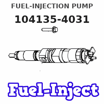
Information fuel-injection pump
BOSCH
9 410 618 369
9410618369
ZEXEL
104135-4031
1041354031
ISHIKAWAJIMA-S
131017800
131017800
Rating:
Compare Prices: .
As an associate, we earn commssions on qualifying purchases through the links below

SINOCMP 104135-4030 131017800 9410617920 Fuel Injection Pump for Perkins 404D-22 404C-22 Engine & for New Holland L160 L170 L175 L218 LS160 LS170 Skid Steer Loader
SINOCMP 【Accurate】installation and use our excavator parts. Please find the suitable product based on the old part number and machine model. || 【Scientific】products pass professional testing and inspection. Not sure what the construction machinery product will do? The adaptable products, safe using operation and easy installation. || 【Use】construction machinery product must be in accordance with operating procedures to avoid accidents. We will provide matching product usage guidance and professional product operation suggestions. || 【Key】construction machinery equipment meaning of existence? It is to bring convenience to life. In order to avoid the trouble of frequent replacement, strictly require product quality and improve service life. || 【Part Number】104135-4030 131017800 9410617920
SINOCMP 【Accurate】installation and use our excavator parts. Please find the suitable product based on the old part number and machine model. || 【Scientific】products pass professional testing and inspection. Not sure what the construction machinery product will do? The adaptable products, safe using operation and easy installation. || 【Use】construction machinery product must be in accordance with operating procedures to avoid accidents. We will provide matching product usage guidance and professional product operation suggestions. || 【Key】construction machinery equipment meaning of existence? It is to bring convenience to life. In order to avoid the trouble of frequent replacement, strictly require product quality and improve service life. || 【Part Number】104135-4030 131017800 9410617920

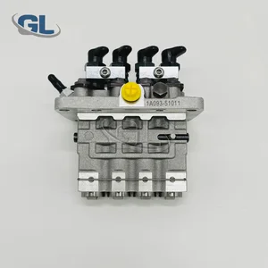
Original Fuel Injection Pump Compatible With Kubota Perkins 131017800 104135-4031 9410618369 Excavator Engine Replacement Parts
YERCBX Integrated design: Compact structure, small space occupation, and convenient for vehicle installation and layout. || Easy maintenance: The design is reasonable, and daily inspection and maintenance operations are simple, saving time || Lightweight design: Reducing its own weight helps to achieve overall lightweighting of the vehicle || The installation interface design is convenient for installation and saves installation time. || Modular design: Facilitates maintenance and replacement of damaged parts, reducing maintenance costs.
YERCBX Integrated design: Compact structure, small space occupation, and convenient for vehicle installation and layout. || Easy maintenance: The design is reasonable, and daily inspection and maintenance operations are simple, saving time || Lightweight design: Reducing its own weight helps to achieve overall lightweighting of the vehicle || The installation interface design is convenient for installation and saves installation time. || Modular design: Facilitates maintenance and replacement of damaged parts, reducing maintenance costs.

New Fuel Injection Pump Compatible For Kubota Perkins 131017800 104135-4031 9410618369 Excavator Engine Replacement Parts
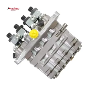
TBEFQVAW Lightweight design: effectively reduces vehicle load, improves fuel economy, and facilitates installation and handling || Multi specification adaptation: providing multiple flow specifications and models to meet the needs of different displacement engines || Adaptive installation: Standardized interface design, compatible with 95% of mainstream engine models, no need for complex modifications || Anti corrosion coating: The surface of key components is covered with anti-corrosion coating, which is not afraid of humid coastal environments and harsh weather conditions || New Fuel Injection Pump Compatible For Kubota Perkins 131017800 104135-4031 9410618369 Excavator Engine Replacement Parts
TBEFQVAW Lightweight design: effectively reduces vehicle load, improves fuel economy, and facilitates installation and handling || Multi specification adaptation: providing multiple flow specifications and models to meet the needs of different displacement engines || Adaptive installation: Standardized interface design, compatible with 95% of mainstream engine models, no need for complex modifications || Anti corrosion coating: The surface of key components is covered with anti-corrosion coating, which is not afraid of humid coastal environments and harsh weather conditions || New Fuel Injection Pump Compatible For Kubota Perkins 131017800 104135-4031 9410618369 Excavator Engine Replacement Parts
You can express buy:
USD 392.84
30-06-2025
30-06-2025
China Made New Fuel Injection Pump Head 131017800 104135-4031 Fits for Perkins
USD 892.12
14-06-2025
14-06-2025
Dieseal Fuel Injection Pump 131017800 104135-4030 For Perkins Engine 404D-22 404C-22 New Holland TC35/40/45 Ford Loader
Images:
USD 579.51

[28-Apr-2025]
Components :
| 0. | INJECTION-PUMP ASSEMBLY | 104135-4031 |
| 1. | _ | |
| 2. | FUEL INJECTION PUMP | |
| 3. | NUMBER PLATE | |
| 4. | _ | |
| 5. | CAPSULE | |
| 6. | ADJUSTING DEVICE | |
| 7. | NOZZLE AND HOLDER ASSY | 105148-1170 |
| 8. | Nozzle and Holder | |
| 9. | Open Pre:MPa(Kqf/cm2) | 14.7(150) |
| 10. | NOZZLE-HOLDER | 105078-0100 |
| 11. | NOZZLE | 105007-1170 |
Scheme ###:
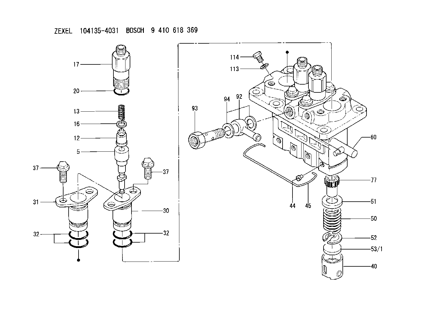
| 5. | [4] | 140163-2020 | PLUNGER-AND-BARREL ASSY |
| 12. | [4] | 140110-3620 | DELIVERY-VALVE ASSEMBLY |
| 13. | [4] | 140112-2900 | COMPRESSION SPRING |
| 16. | [4] | 140115-1400 | GASKET |
| 17. | [4] | 140116-7520 | FITTING |
| 20. | [4] | 016500-1520 | O-RING |
| 30. | [3] | 140131-0521 | FLANGE BUSHING |
| 31. | [1] | 140131-1021 | FLANGE BUSHING |
| 32. | [8] | 016550-1920 | O-RING |
| 32. | [8] | 016550-1920 | O-RING |
| 37. | [8] | 140124-0200 | BLEEDER SCREW |
| 37. | [8] | 140124-0200 | BLEEDER SCREW |
| 40. | [4] | 140200-2620 | TAPPET |
| 44. | [4] | 140212-0300 | BEARING PIN |
| 45. | [1] | 140213-1500 | LOCKING WASHER |
| 50. | [4] | 140215-1900 | COMPRESSION SPRING |
| 51. | [4] | 140216-0800 | SLOTTED WASHER |
| 52. | [4] | 140217-2200 | SLOTTED WASHER |
| 53/1. | [1] | 140217-5000 | PLATE D19T2.60 |
| 53/1. | [1] | 140217-5100 | PLATE D19T2.65 |
| 53/1. | [1] | 140217-5200 | PLATE D19T2.70 |
| 53/1. | [1] | 140217-5300 | PLATE D19T2.75 |
| 53/1. | [1] | 140217-5400 | PLATE D19T2.80 |
| 53/1. | [1] | 140217-5500 | PLATE D19T2.85 |
| 53/1. | [1] | 140217-5600 | PLATE D19T2.90 |
| 53/1. | [1] | 140217-5700 | PLATE D19T2.95 |
| 53/1. | [1] | 140217-5800 | PLATE D19T3.00 |
| 53/1. | [1] | 140217-5900 | PLATE D19T3.05 |
| 53/1. | [1] | 140217-6000 | PLATE D19T3.10 |
| 53/1. | [1] | 140217-6100 | PLATE D19T3.15 |
| 53/1. | [1] | 140217-6200 | PLATE D19T3.20 |
| 53/1. | [1] | 140217-6300 | PLATE D19T3.25 |
| 53/1. | [1] | 140217-6400 | PLATE D19T3.30 |
| 53/1. | [1] | 140217-6500 | PLATE D19T3.35 |
| 53/1. | [1] | 140217-6600 | PLATE D19T3.40 |
| 53/1. | [1] | 140217-6700 | PLATE D19T3.45 |
| 53/1. | [1] | 140217-6800 | PLATE D19T3.50 |
| 53/1. | [1] | 140217-6900 | PLATE D19T3.55 |
| 53/1. | [1] | 140217-7000 | PLATE D19T3.60 |
| 53/1. | [1] | 140217-7100 | PLATE D19T3.65 |
| 53/1. | [1] | 140217-7200 | PLATE D19T3.70 |
| 53/1. | [1] | 140217-7300 | PLATE D19T3.75 |
| 53/1. | [1] | 140217-7400 | PLATE D19T3.80 |
| 53/1. | [1] | 140217-7500 | PLATE D19T3.85 |
| 53/1. | [1] | 140217-7600 | PLATE D19T3.90 |
| 53/1. | [1] | 140217-7700 | PLATE D19T3.95 |
| 53/1. | [1] | 140217-7800 | PLATE D19T4.00 |
| 53/1. | [1] | 140217-7900 | PLATE D19T4.05 |
| 53/1. | [1] | 140217-8000 | PLATE D19T4.10 |
| 53/1. | [1] | 140253-2000 | PLATE |
| 53/1. | [1] | 140253-2100 | PLATE |
| 53/1. | [1] | 140253-2200 | PLATE |
| 53/1. | [1] | 140253-2300 | PLATE |
| 53/1. | [1] | 140253-2400 | PLATE |
| 53/1. | [1] | 140253-2500 | PLATE |
| 53/1. | [1] | 140253-2600 | PLATE |
| 53/1. | [1] | 140253-2700 | PLATE |
| 53/1. | [1] | 140253-2800 | PLATE |
| 53/1. | [1] | 140253-2900 | PLATE |
| 53/1. | [1] | 140253-3000 | PLATE |
| 53/1. | [1] | 140253-3100 | PLATE |
| 53/1. | [1] | 140253-3200 | PLATE |
| 53/1. | [1] | 140253-3300 | PLATE |
| 53/1. | [1] | 140253-3400 | PLATE |
| 53/1. | [1] | 140253-3500 | PLATE |
| 53/1. | [1] | 140253-3600 | PLATE |
| 53/1. | [1] | 140253-3700 | PLATE |
| 53/1. | [1] | 140253-3800 | PLATE |
| 53/1. | [1] | 140253-3900 | PLATE |
| 53/1. | [1] | 140253-4000 | PLATE |
| 53/1. | [1] | 140253-4100 | PLATE |
| 53/1. | [1] | 140253-4200 | PLATE |
| 53/1. | [1] | 140253-4300 | PLATE |
| 53/1. | [1] | 140253-4400 | PLATE |
| 53/1. | [1] | 140253-4500 | PLATE |
| 53/1. | [1] | 140253-4600 | PLATE |
| 53/1. | [1] | 140253-4700 | PLATE |
| 53/1. | [1] | 140253-4800 | PLATE |
| 53/1. | [1] | 140253-4900 | PLATE |
| 60. | [1] | 140243-5620 | CONTROL RACK |
| 77. | [4] | 140241-2700 | CONTROL SLEEVE |
| 92. | [1] | 029711-2050 | INLET UNION |
| 93. | [1] | 140402-1300 | EYE BOLT |
| 94. | [2] | 026512-1540 | GASKET D15.4&12.2T1.50 |
| 113. | [1] | 026508-1240 | GASKET D11.9&8.2T1 |
| 114. | [1] | 140420-1400 | BLEEDER SCREW |
Include in #2:
104135-4031
as INJECTION-PUMP ASSEMBLY
Cross reference number
Zexel num
Bosch num
Firm num
Name
131017800 ISHIKAWAJIMA-S
FUEL-INJECTION PUMP
K 23AD FUEL INJECTION PUMP PFR-4KX PFR
K 23AD FUEL INJECTION PUMP PFR-4KX PFR
Information:
1. Remove six bolts (1) and remove the fan.2. Loosen the fan belts and alternator belts. Remove the belts. 3. Remove four bolts (3) and adjusting bolt (2). Remove the fan drive.Install Fan Drive
1. Put the fan drive in position on the engine and install the four bolts.2. Install the adjusting bolt. Install the fan and alternator belts. Make an adjustment to the tension. The correct belt tension is 7/8 in. (22 mm) movement for used belts and 3/4in. (19 mm) movement for new belts when measured with the application of a 25 lb. (11 kg) force half way between the two pulleys.3. Tighten the four fan drive bolts.4. Install the fan with the six bolts.Disassemble Fan Drive
start by: a) remove fan drive 1. Remove two bolts and washers (2). Remove hub (1). 2. Bend down the lock plate and remove bolts (4). Remove the lock plate and washer (3). 3. Use tool (A) to remove the pulley from the bracket assembly. 4. Remove the two bearings and the seal with tool (B).5. Remove the spacer.Assemble Fan Drive
1. Put multipurpose grease on the seal. Install the seal on the pulley with tool (A).2. Install the pulley in the bracket assembly. Fill half the space between the two bearings with multipurpose grease.3. Heat two bearings in oil. The temperature of the oil must be 300° 25°F (149° 14°C).
The bearing heating oil used to heat the bearings must have a flash point above 400°F (204°C).
4. Put multipurpose grease on the bearings. Install the bearing, spacer and bearing with tool (A). 5. Install the washer, lock plate and two bolts. Bend the lock plate up.6. Install the hub with the two bolts and lockwashers.end by: a) install fan drive