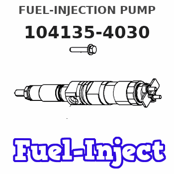
Information fuel-injection pump
BOSCH
9 410 617 920
9410617920
ZEXEL
104135-4030
1041354030
Rating:
Compare Prices: .
As an associate, we earn commssions on qualifying purchases through the links below

Fuel Injection Pump Compatible For Kubota Ford New Holland Loader L160 C175 L170 L175 TT45A 104135-4030 9410617920 Excavator Engine Parts
Xqscvqwfa Part Number:104135-4030 9410617920 || Easy Installation:Designed for hassle-free replacement with no modifications required. || Enhanced Durability:Robust construction with high-grade materials for long-lasting reliability. || Improved Fuel Efficiency:Maintains consistent fuel pressure for better combustion and reduced emissions. || Premium Quality:Precision-engineered for optimal fuel pressure and flow, ensuring smooth engine performance.
Xqscvqwfa Part Number:104135-4030 9410617920 || Easy Installation:Designed for hassle-free replacement with no modifications required. || Enhanced Durability:Robust construction with high-grade materials for long-lasting reliability. || Improved Fuel Efficiency:Maintains consistent fuel pressure for better combustion and reduced emissions. || Premium Quality:Precision-engineered for optimal fuel pressure and flow, ensuring smooth engine performance.

Fuel Injection Pump Compatible For Kubota Ford New Holland Loader L160 C175 L170 L175 TT45A 104135-4030 9410617920 Excavator Engine Parts
TBEFQVAW Lightweight design: effectively reduces vehicle load, improves fuel economy, and facilitates installation and handling || Multi specification adaptation: providing multiple flow specifications and models to meet the needs of different displacement engines || Adaptive installation: Standardized interface design, compatible with 95% of mainstream engine models, no need for complex modifications || Anti corrosion coating: The surface of key components is covered with anti-corrosion coating, which is not afraid of humid coastal environments and harsh weather conditions || Fuel Injection Pump Compatible For Kubota Ford New Holland Loader L160 C175 L170 L175 TT45A 104135-4030 9410617920 Excavator Engine Parts
TBEFQVAW Lightweight design: effectively reduces vehicle load, improves fuel economy, and facilitates installation and handling || Multi specification adaptation: providing multiple flow specifications and models to meet the needs of different displacement engines || Adaptive installation: Standardized interface design, compatible with 95% of mainstream engine models, no need for complex modifications || Anti corrosion coating: The surface of key components is covered with anti-corrosion coating, which is not afraid of humid coastal environments and harsh weather conditions || Fuel Injection Pump Compatible For Kubota Ford New Holland Loader L160 C175 L170 L175 TT45A 104135-4030 9410617920 Excavator Engine Parts

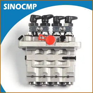
SINOCMP 104135-4030 131017800 9410617920 Fuel Injection Pump for Perkins 404D-22 404C-22 Engine & for New Holland L160 L170 L175 L218 LS160 LS170 Skid Steer Loader
SINOCMP 【Accurate】installation and use our excavator parts. Please find the suitable product based on the old part number and machine model. || 【Scientific】products pass professional testing and inspection. Not sure what the construction machinery product will do? The adaptable products, safe using operation and easy installation. || 【Use】construction machinery product must be in accordance with operating procedures to avoid accidents. We will provide matching product usage guidance and professional product operation suggestions. || 【Key】construction machinery equipment meaning of existence? It is to bring convenience to life. In order to avoid the trouble of frequent replacement, strictly require product quality and improve service life. || 【Part Number】104135-4030 131017800 9410617920
SINOCMP 【Accurate】installation and use our excavator parts. Please find the suitable product based on the old part number and machine model. || 【Scientific】products pass professional testing and inspection. Not sure what the construction machinery product will do? The adaptable products, safe using operation and easy installation. || 【Use】construction machinery product must be in accordance with operating procedures to avoid accidents. We will provide matching product usage guidance and professional product operation suggestions. || 【Key】construction machinery equipment meaning of existence? It is to bring convenience to life. In order to avoid the trouble of frequent replacement, strictly require product quality and improve service life. || 【Part Number】104135-4030 131017800 9410617920
You can express buy:
USD 1300.28
23-06-2025
23-06-2025
Hot saleFuel Pump 104135-4030 104135-4020 104134-4060 306-6346 for Zexel CAT 304.5 Excavator C2.2 3024 3024C Engine
USD 530.03
14-06-2025
14-06-2025
Fuel Pump 104135-4030 1041354030 9410617920 For Kubota Ford Perkins Shibaura New Holland 404D-22 N844 TC35 TC40 TC45
Images:
USD 892.12

[14-Jun-2025]
USD 598.69

[07-May-2025]
USD 516.12

[05-May-2025]
Components :
| 0. | INJECTION-PUMP ASSEMBLY | 104135-4030 |
| 1. | _ | |
| 2. | FUEL INJECTION PUMP | |
| 3. | NUMBER PLATE | |
| 4. | _ | |
| 5. | CAPSULE | |
| 6. | ADJUSTING DEVICE | |
| 7. | NOZZLE AND HOLDER ASSY | 105148-1170 |
| 8. | Nozzle and Holder | |
| 9. | Open Pre:MPa(Kqf/cm2) | 14.7{150} |
| 10. | NOZZLE-HOLDER | 105078-0100 |
| 11. | NOZZLE | 105007-1170 |
Scheme ###:
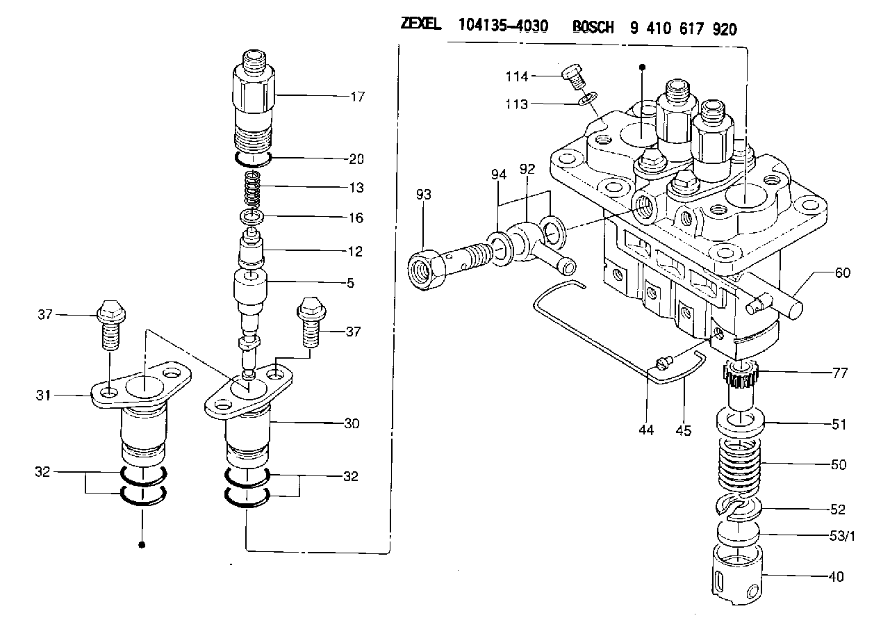
| 5. | [4] | 140163-2020 | PLUNGER-AND-BARREL ASSY |
| 12. | [4] | 140110-3620 | DELIVERY-VALVE ASSEMBLY |
| 13. | [4] | 140112-2900 | COMPRESSION SPRING |
| 16. | [4] | 140115-1400 | GASKET |
| 17. | [4] | 140116-7520 | FITTING |
| 20. | [4] | 016500-1520 | O-RING |
| 30. | [3] | 140131-0521 | FLANGE BUSHING |
| 31. | [1] | 140131-1021 | FLANGE BUSHING |
| 32. | [8] | 016550-1920 | O-RING |
| 32. | [8] | 016550-1920 | O-RING |
| 37. | [8] | 140124-0200 | BLEEDER SCREW |
| 37. | [8] | 140124-0200 | BLEEDER SCREW |
| 40. | [4] | 140200-2620 | TAPPET |
| 44. | [4] | 140212-0300 | BEARING PIN |
| 45. | [1] | 140213-1500 | LOCKING WASHER |
| 50. | [4] | 140215-1900 | COMPRESSION SPRING |
| 51. | [4] | 140216-0800 | SLOTTED WASHER |
| 52. | [4] | 140217-2200 | SLOTTED WASHER |
| 53/1. | [1] | 140217-5000 | PLATE D19T2.60 |
| 53/1. | [1] | 140217-5100 | PLATE D19T2.65 |
| 53/1. | [1] | 140217-5200 | PLATE D19T2.70 |
| 53/1. | [1] | 140217-5300 | PLATE D19T2.75 |
| 53/1. | [1] | 140217-5400 | PLATE D19T2.80 |
| 53/1. | [1] | 140217-5500 | PLATE D19T2.85 |
| 53/1. | [1] | 140217-5600 | PLATE D19T2.90 |
| 53/1. | [1] | 140217-5700 | PLATE D19T2.95 |
| 53/1. | [1] | 140217-5800 | PLATE D19T3.00 |
| 53/1. | [1] | 140217-5900 | PLATE D19T3.05 |
| 53/1. | [1] | 140217-6000 | PLATE D19T3.10 |
| 53/1. | [1] | 140217-6100 | PLATE D19T3.15 |
| 53/1. | [1] | 140217-6200 | PLATE D19T3.20 |
| 53/1. | [1] | 140217-6300 | PLATE D19T3.25 |
| 53/1. | [1] | 140217-6400 | PLATE D19T3.30 |
| 53/1. | [1] | 140217-6500 | PLATE D19T3.35 |
| 53/1. | [1] | 140217-6600 | PLATE D19T3.40 |
| 53/1. | [1] | 140217-6700 | PLATE D19T3.45 |
| 53/1. | [1] | 140217-6800 | PLATE D19T3.50 |
| 53/1. | [1] | 140217-6900 | PLATE D19T3.55 |
| 53/1. | [1] | 140217-7000 | PLATE D19T3.60 |
| 53/1. | [1] | 140217-7100 | PLATE D19T3.65 |
| 53/1. | [1] | 140217-7200 | PLATE D19T3.70 |
| 53/1. | [1] | 140217-7300 | PLATE D19T3.75 |
| 53/1. | [1] | 140217-7400 | PLATE D19T3.80 |
| 53/1. | [1] | 140217-7500 | PLATE D19T3.85 |
| 53/1. | [1] | 140217-7600 | PLATE D19T3.90 |
| 53/1. | [1] | 140217-7700 | PLATE D19T3.95 |
| 53/1. | [1] | 140217-7800 | PLATE D19T4.00 |
| 53/1. | [1] | 140217-7900 | PLATE D19T4.05 |
| 53/1. | [1] | 140217-8000 | PLATE D19T4.10 |
| 53/1. | [1] | 140253-2000 | PLATE |
| 53/1. | [1] | 140253-2100 | PLATE |
| 53/1. | [1] | 140253-2200 | PLATE |
| 53/1. | [1] | 140253-2300 | PLATE |
| 53/1. | [1] | 140253-2400 | PLATE |
| 53/1. | [1] | 140253-2500 | PLATE |
| 53/1. | [1] | 140253-2600 | PLATE |
| 53/1. | [1] | 140253-2700 | PLATE |
| 53/1. | [1] | 140253-2800 | PLATE |
| 53/1. | [1] | 140253-2900 | PLATE |
| 53/1. | [1] | 140253-3000 | PLATE |
| 53/1. | [1] | 140253-3100 | PLATE |
| 53/1. | [1] | 140253-3200 | PLATE |
| 53/1. | [1] | 140253-3300 | PLATE |
| 53/1. | [1] | 140253-3400 | PLATE |
| 53/1. | [1] | 140253-3500 | PLATE |
| 53/1. | [1] | 140253-3600 | PLATE |
| 53/1. | [1] | 140253-3700 | PLATE |
| 53/1. | [1] | 140253-3800 | PLATE |
| 53/1. | [1] | 140253-3900 | PLATE |
| 53/1. | [1] | 140253-4000 | PLATE |
| 53/1. | [1] | 140253-4100 | PLATE |
| 53/1. | [1] | 140253-4200 | PLATE |
| 53/1. | [1] | 140253-4300 | PLATE |
| 53/1. | [1] | 140253-4400 | PLATE |
| 53/1. | [1] | 140253-4500 | PLATE |
| 53/1. | [1] | 140253-4600 | PLATE |
| 53/1. | [1] | 140253-4700 | PLATE |
| 53/1. | [1] | 140253-4800 | PLATE |
| 53/1. | [1] | 140253-4900 | PLATE |
| 60. | [1] | 140243-5620 | CONTROL RACK |
| 77. | [4] | 140241-2700 | CONTROL SLEEVE |
| 92. | [1] | 029711-2050 | INLET UNION |
| 93. | [1] | 140402-1300 | EYE BOLT |
| 94. | [2] | 026512-1540 | GASKET D15.4&12.2T1.50 |
| 113. | [1] | 026508-1240 | GASKET D11.9&8.2T1 |
| 114. | [1] | 140420-1400 | BLEEDER SCREW |
Include in #2:
104135-4030
as INJECTION-PUMP ASSEMBLY
Cross reference number
Zexel num
Bosch num
Firm num
Name
FUEL-INJECTION PUMP
* K 23AD FUEL INJECTION PUMP PFR-4KX PFR
* K 23AD FUEL INJECTION PUMP PFR-4KX PFR
Information:
2. Remove bolts (1).3. Remove the water hose from the bottom of the water pump.4. Loosen the water hose clamps from water pipe (2).5. Remove two bolts (3) and remove the water pump and elbow as a unit.Install Water Pump
1. Inspect all O-rings, gaskets and hoses and install new parts if needed.2. Put the water pump and elbow in position and install the bolts.3. Install the water hose and tighten all water hose clamps.4. Fill the cooling system to the correct level.Disassemble Water Pump
start by:a) remove water pump1. Remove cover (3) and gasket from water pump (1).2. Remove elbow (2) and gasket from water pump (1). 3. Loosen bolt (5) .25 in. (6.35 mm). Hit (tap) the bolt with a soft hammer to remove impeller (4) from the shaft. 4. Remove spring and seal assembly (7) from shaft (6). 5. Turn the water pump over and remove bolt (8) and lockwasher.6. Remove O-ring seal (9) from the housing. 7. Use tooling (A) to remove gear (11) and bearing (10) from the water pump.8. Remove bearing (10) from gear (11). 9. Remove snap ring (12) with tool (B). 10. Remove bearing (14) and shaft (13) as a unit.11. Use tool (C) and a press to remove bearing (14) from the shaft. 12. Remove the ceramic ring and seal (15) from the housing. 13. Remove the lip type seal (16) from the housing with tooling (D).Assemble Water Pump
The seal must be installed with the lip toward the bearings.1. Install the lip type seal in housing (1) with tooling (A) to the bottom of the seal counterbore. Put a thin layer of engine oil on the lip of the seal. 2. Use a press to install shaft (2) in bearing (3). 3. Install the shaft and bearing (3) in housing (1). 4. Install snap ring (4) in the housing with tool (B). 5. Install bearing (5) on gear (6).
When gear (6) is installed, make sure the pins on the gear engage the holes in the shaft.
6. Put gear (6) and bearing in position on the shaft and install washer and bolt. 7. Install O-ring seal (7) on the housing.
Clean water only is permitted for use as a lubricant to make assembly easier. Do not damage or put hands on the wear surface of the carbon ring or the ceramic ring. Install the ceramic ring with the smoothest face of the ring toward the carbon seal assembly.
8. Put the ceramic ring (8) in position in the rubber seal. Use hand pressure and tool (which is with the replacement ring) to install the ceramic ring and rubber seal. 9. Remove the spring from the seal assembly (9). Use hand pressure and the tool (which is with the replacement ring) to install the seal assembly. Push seal assembly on the shaft until seal faces make light contact. 10. Install spring (10) on the seal assembly. 11. Put impeller (11) in position on the shaft. 12. Install washer and bolt (12). Tighten the bolt to