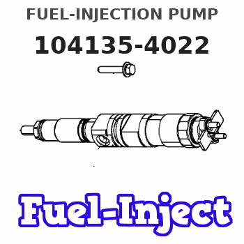
Information fuel-injection pump
BOSCH
9 410 618 467
9410618467
ZEXEL
104135-4022
1041354022
ISHIKAWAJIMA-S
131017741
131017741
Rating:
Compare Prices: .
As an associate, we earn commssions on qualifying purchases through the links below

IMIFAFTAbT SBA131017741 104135-4020 104135-4022 Cylinder Block for Shibaura N844 Engine for New Holland Tractor 3415 TC45 TC45D TC45DA TC55DA for Case-IH Tractor D35 D40 D45 DX35 DX40 DX45 DX55
IMIFAFTAbT Part Name:Cylinder Block SBA131017741 104135-4020 104135-4022 || Part Number:SBA131017741 104135-4020 104135-4022 || APPlication: Compatible with Shibaura N844 Engine for New Holland Tractor 3415 TC45 TC45D TC45DA TC55DA for Case-IH Tractor D35 D40 D45 DX35 DX40 DX45 DX55 || If you are not sure if the product is suitable please leave us a message and send us your original || product picture and part number and we will send the correct part after confirmation
IMIFAFTAbT Part Name:Cylinder Block SBA131017741 104135-4020 104135-4022 || Part Number:SBA131017741 104135-4020 104135-4022 || APPlication: Compatible with Shibaura N844 Engine for New Holland Tractor 3415 TC45 TC45D TC45DA TC55DA for Case-IH Tractor D35 D40 D45 DX35 DX40 DX45 DX55 || If you are not sure if the product is suitable please leave us a message and send us your original || product picture and part number and we will send the correct part after confirmation

$639.90
09 Dec 2024
CA: HIRINTOL-shop
131017741 SBA131017741 Fuel Injection Pump for Perkins 404D-22 404C-22 Ford New Holland Case-IH TC35 TC45DA TC55DA D35 D40 D45 DX35 DX40 DX45 DX55
HIRINTOL 🔸Replace Part Number: 131017741 SBA131017741 || 🔸Engine Model: for Perkins Engine 404D-22 404D-22T 404D-22TA 404C-22 404C-22T; for Shibaura Engine: N844, ISM N844 || 🔸Compatible Model: for New Holland Tractors TC45 TC45D TC45DA TC55DA; Case-IH Tractor D35 D40 D45 DX35 DX40 DX45 DX55 || 🔸Efficient And Stable: Using advanced technology, it can provide efficient and stable fuel supply to ensure the normal operation of the vehicle. || 🔸Durable And Reliable: Tested and proven many times, it has a long life and reliable quality to keep working under extreme conditions.
HIRINTOL 🔸Replace Part Number: 131017741 SBA131017741 || 🔸Engine Model: for Perkins Engine 404D-22 404D-22T 404D-22TA 404C-22 404C-22T; for Shibaura Engine: N844, ISM N844 || 🔸Compatible Model: for New Holland Tractors TC45 TC45D TC45DA TC55DA; Case-IH Tractor D35 D40 D45 DX35 DX40 DX45 DX55 || 🔸Efficient And Stable: Using advanced technology, it can provide efficient and stable fuel supply to ensure the normal operation of the vehicle. || 🔸Durable And Reliable: Tested and proven many times, it has a long life and reliable quality to keep working under extreme conditions.

$619.90
29 Dec 2024
CN: IMELBUFF Excavator P
IMELBUFF 131017741 104135-4022 9410618467 Fuel Injection Pump for Perkins 404C-22 404D-22 Engine New Holland Tractor TC45 TC45D TC45DA TC55DA Case Tractor D35 D40 D45 DX35 DX40 DX45 DX55
IMELBUFF 🚜Part Number: 131017741 104135-4022 9410618467 || 🚜Engine Model: for Perkins 404C-22 404D-22 Engine || 🚜Vehicle Application: for Case-IH Tractor D35 D40 D45 DX35 DX40 DX45 DX55; for New Holland Tractors TC45 TC45D TC45DA TC55DA || 🚜Warm Tips: Please check your part numbers before placing an order. If you are not sure, you can send us your engine model or fuel pump part number || 🚜Service: 5-months warranty and 24 hour support for customer service. Please feel free to contact us by email if you have any question with the product
IMELBUFF 🚜Part Number: 131017741 104135-4022 9410618467 || 🚜Engine Model: for Perkins 404C-22 404D-22 Engine || 🚜Vehicle Application: for Case-IH Tractor D35 D40 D45 DX35 DX40 DX45 DX55; for New Holland Tractors TC45 TC45D TC45DA TC55DA || 🚜Warm Tips: Please check your part numbers before placing an order. If you are not sure, you can send us your engine model or fuel pump part number || 🚜Service: 5-months warranty and 24 hour support for customer service. Please feel free to contact us by email if you have any question with the product
You can express buy:
USD 393.12
01-07-2025
01-07-2025
China Made New Fuel Injection Pump Head 131017741 104135-4022 Fits for Perkins
Components :
| 0. | INJECTION-PUMP ASSEMBLY | 104135-4022 |
| 1. | _ | |
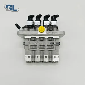
| 2. | FUEL INJECTION PUMP | |
| 3. | NUMBER PLATE | |
| 4. | _ | |
| 5. | CAPSULE | |
| 6. | ADJUSTING DEVICE | |
| 7. | NOZZLE AND HOLDER ASSY | 105148-1170 |
| 8. | Nozzle and Holder | |
| 9. | Open Pre:MPa(Kqf/cm2) | 14.7(150) |
| 10. | NOZZLE-HOLDER | 105078-0100 |
| 11. | NOZZLE | 105007-1170 |
Scheme ###:
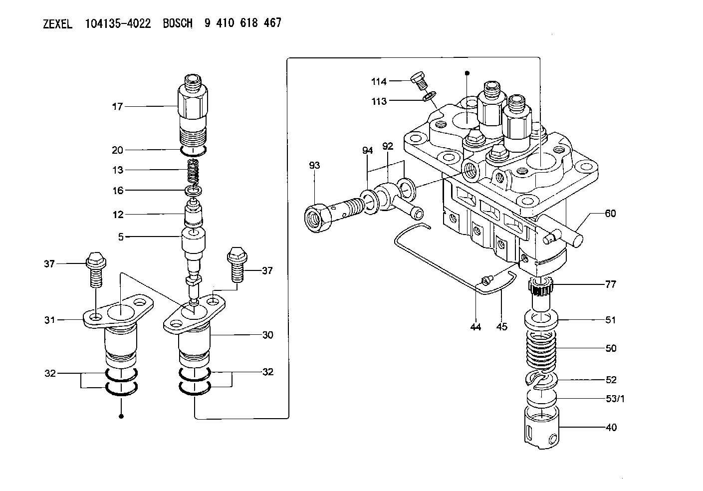
| 5. | [4] | 140163-1520 | PLUNGER-AND-BARREL ASSY |
| 12. | [4] | 140110-3620 | DELIVERY-VALVE ASSEMBLY |
| 13. | [4] | 140112-2900 | COMPRESSION SPRING |
| 16. | [4] | 140115-1400 | GASKET |
| 17. | [4] | 140116-7520 | FITTING |
| 20. | [4] | 140118-0301 | O-RING |
| 30. | [3] | 140131-0521 | FLANGE BUSHING |
| 31. | [1] | 140131-1021 | FLANGE BUSHING |
| 32. | [8] | 140118-0201 | O-RING |
| 32. | [8] | 140118-0201 | O-RING |
| 37. | [8] | 140124-0200 | BLEEDER SCREW |
| 37. | [8] | 140124-0200 | BLEEDER SCREW |
| 40. | [4] | 140200-2620 | TAPPET |
| 44. | [4] | 140212-0300 | BEARING PIN |
| 45. | [1] | 140213-1500 | LOCKING WASHER |
| 50. | [4] | 140215-1900 | COMPRESSION SPRING |
| 51. | [4] | 140216-0800 | SLOTTED WASHER |
| 52. | [4] | 140217-2200 | SLOTTED WASHER |
| 53/1. | [1] | 140217-5000 | PLATE D19T2.60 |
| 53/1. | [1] | 140217-5100 | PLATE D19T2.65 |
| 53/1. | [1] | 140217-5200 | PLATE D19T2.70 |
| 53/1. | [1] | 140217-5300 | PLATE D19T2.75 |
| 53/1. | [1] | 140217-5400 | PLATE D19T2.80 |
| 53/1. | [1] | 140217-5500 | PLATE D19T2.85 |
| 53/1. | [1] | 140217-5600 | PLATE D19T2.90 |
| 53/1. | [1] | 140217-5700 | PLATE D19T2.95 |
| 53/1. | [1] | 140217-5800 | PLATE D19T3.00 |
| 53/1. | [1] | 140217-5900 | PLATE D19T3.05 |
| 53/1. | [1] | 140217-6000 | PLATE D19T3.10 |
| 53/1. | [1] | 140217-6100 | PLATE D19T3.15 |
| 53/1. | [1] | 140217-6200 | PLATE D19T3.20 |
| 53/1. | [1] | 140217-6300 | PLATE D19T3.25 |
| 53/1. | [1] | 140217-6400 | PLATE D19T3.30 |
| 53/1. | [1] | 140217-6500 | PLATE D19T3.35 |
| 53/1. | [1] | 140217-6600 | PLATE D19T3.40 |
| 53/1. | [1] | 140217-6700 | PLATE D19T3.45 |
| 53/1. | [1] | 140217-6800 | PLATE D19T3.50 |
| 53/1. | [1] | 140217-6900 | PLATE D19T3.55 |
| 53/1. | [1] | 140217-7000 | PLATE D19T3.60 |
| 53/1. | [1] | 140217-7100 | PLATE D19T3.65 |
| 53/1. | [1] | 140217-7200 | PLATE D19T3.70 |
| 53/1. | [1] | 140217-7300 | PLATE D19T3.75 |
| 53/1. | [1] | 140217-7400 | PLATE D19T3.80 |
| 53/1. | [1] | 140217-7500 | PLATE D19T3.85 |
| 53/1. | [1] | 140217-7600 | PLATE D19T3.90 |
| 53/1. | [1] | 140217-7700 | PLATE D19T3.95 |
| 53/1. | [1] | 140217-7800 | PLATE D19T4.00 |
| 53/1. | [1] | 140217-7900 | PLATE D19T4.05 |
| 53/1. | [1] | 140217-8000 | PLATE D19T4.10 |
| 53/1. | [1] | 140253-2000 | PLATE |
| 53/1. | [1] | 140253-2100 | PLATE |
| 53/1. | [1] | 140253-2200 | PLATE |
| 53/1. | [1] | 140253-2300 | PLATE |
| 53/1. | [1] | 140253-2400 | PLATE |
| 53/1. | [1] | 140253-2500 | PLATE |
| 53/1. | [1] | 140253-2600 | PLATE |
| 53/1. | [1] | 140253-2700 | PLATE |
| 53/1. | [1] | 140253-2800 | PLATE |
| 53/1. | [1] | 140253-2900 | PLATE |
| 53/1. | [1] | 140253-3000 | PLATE |
| 53/1. | [1] | 140253-3100 | PLATE |
| 53/1. | [1] | 140253-3200 | PLATE |
| 53/1. | [1] | 140253-3300 | PLATE |
| 53/1. | [1] | 140253-3400 | PLATE |
| 53/1. | [1] | 140253-3500 | PLATE |
| 53/1. | [1] | 140253-3600 | PLATE |
| 53/1. | [1] | 140253-3700 | PLATE |
| 53/1. | [1] | 140253-3800 | PLATE |
| 53/1. | [1] | 140253-3900 | PLATE |
| 53/1. | [1] | 140253-4000 | PLATE |
| 53/1. | [1] | 140253-4100 | PLATE |
| 53/1. | [1] | 140253-4200 | PLATE |
| 53/1. | [1] | 140253-4300 | PLATE |
| 53/1. | [1] | 140253-4400 | PLATE |
| 53/1. | [1] | 140253-4500 | PLATE |
| 53/1. | [1] | 140253-4600 | PLATE |
| 53/1. | [1] | 140253-4700 | PLATE |
| 53/1. | [1] | 140253-4800 | PLATE |
| 53/1. | [1] | 140253-4900 | PLATE |
| 60. | [1] | 140243-5620 | CONTROL RACK |
| 77. | [4] | 140241-2700 | CONTROL SLEEVE |
| 92. | [1] | 029711-2050 | INLET UNION |
| 93. | [1] | 140402-1300 | EYE BOLT |
| 94. | [2] | 026512-1540 | GASKET D15.4&12.2T1.50 |
| 113. | [1] | 026508-1240 | GASKET D11.9&8.2T1 |
| 114. | [1] | 140420-1400 | BLEEDER SCREW |
Include in #1:
106673-7500
as _
Include in #2:
104135-4022
as INJECTION-PUMP ASSEMBLY
Cross reference number
Zexel num
Bosch num
Firm num
Name
Information:
start by: a) remove fuel injection pump housing and governor 1. Install the fuel injection pump housing on tool (A). The fuel filter does not have to be removed to remove the fuel transfer pump.2. Install timing pin (1) to keep the injection pump camshaft from turning during disassembly and assembly. 3. Install bolt (B) in the threads of sleeve (3). Tighten the bolt until the sleeve can be removed.
Do not hit on the bolt or sleeve. This will cause damage to the unit.
4. Remove four bolts (4) that hold the pump body to the housing.5. Remove body (2) from the housing.6. Remove idler gear (6) from the pump body.7. Remove O-ring seal (5) and the two lip-type seals from the body. 8. Remove drive gear (8) from the shaft.9. Remove key (7) from the shaft.Install Fuel Transfer Pump
1. Install the inner seal in the body with tool (A). The lip of the seal must be toward the pump gears.2. Install the outer seal in the body with tool (B). The lip of the seal must be toward the outside.
Always be careful not to scratch or cause damage to the machined surface of the pump body.
3. Install O-ring seal (2) and idler gear (1) on the body. 4. Install the key and drive gear (3) on the shaft. 5. Install body (4) on the housing.6. Install the bolts that hold the body to the housing. 7. Put sleeve (5) in position on the camshaft. Timing pin (6) must be in position as shown to keep the camshaft from turning during assembly.8. Install the sleeve on the camshaft with tool (C).
Do not hit the sleeve with a hammer to install it. This will put end force on the camshaft and cause damage to the other components in the pump housing.
9. The end clearance of the camshaft must be .023 .018 in. (0.58 0.46 mm) after sleeve (5) is installed.end by: a) install fuel injection pump housing and governor.