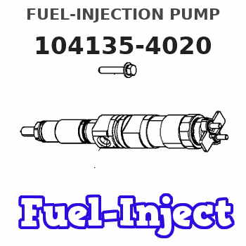
Information fuel-injection pump
BOSCH
9 410 617 890
9410617890
ZEXEL
104135-4020
1041354020
Rating:
Compare Prices: .
As an associate, we earn commssions on qualifying purchases through the links below

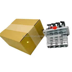
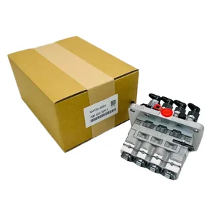
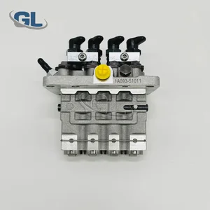
New Fuel Injection Pump Compatible For Kubota Perkins 404C-22 404D-22 104135-4020 9410617890 Excavator Engine Replacement Parts
SDETASOQ Precise control: precise fuel injection, optimized combustion efficiency, reduced fuel consumption, and improved engine power output || Long lifespan and low maintenance: using high-strength wear-resistant alloy materials and corrosion-resistant coatings to reduce maintenance costs and downtime || Stable operation under all operating conditions: tested in extreme environments, continuously stable, and adaptable to various complex road and climate conditions || Silent and efficient operation: Adopting a noise reduction structure, it can maintain quietness even during high-speed operation, without interfering with the driving experience || New Fuel Injection Pump Compatible For Kubota Perkins 404C-22 404D-22 104135-4020 9410617890 Excavator Engine Replacement Parts
SDETASOQ Precise control: precise fuel injection, optimized combustion efficiency, reduced fuel consumption, and improved engine power output || Long lifespan and low maintenance: using high-strength wear-resistant alloy materials and corrosion-resistant coatings to reduce maintenance costs and downtime || Stable operation under all operating conditions: tested in extreme environments, continuously stable, and adaptable to various complex road and climate conditions || Silent and efficient operation: Adopting a noise reduction structure, it can maintain quietness even during high-speed operation, without interfering with the driving experience || New Fuel Injection Pump Compatible For Kubota Perkins 404C-22 404D-22 104135-4020 9410617890 Excavator Engine Replacement Parts

104135-4020 Fuel Injection Pump Compatible for 844 Engine for Holland Tractor 3415 TC48DA TC55DA
JPSMZSC Product Name:Fuel Injection Pump || Part number:104135-4020 || Application:Compatible for 844 Engine for Holland Tractor 3415 TC48DA || Note: Please confirm that the product shown in the part number is what you need. If you cannot confirm, you can leave us a message and provide your engine serial number and nameplate. || Tip: We mainly deal in all parts of the construction machinery series. Our product has stable performance, fast response, high reliability, and easy installation. High quality, most guaranteed. If you have any other requirements, please contact us.
JPSMZSC Product Name:Fuel Injection Pump || Part number:104135-4020 || Application:Compatible for 844 Engine for Holland Tractor 3415 TC48DA || Note: Please confirm that the product shown in the part number is what you need. If you cannot confirm, you can leave us a message and provide your engine serial number and nameplate. || Tip: We mainly deal in all parts of the construction machinery series. Our product has stable performance, fast response, high reliability, and easy installation. High quality, most guaranteed. If you have any other requirements, please contact us.

Original Fuel Injection Pump Compatible With Kubota Perkins 404C-22 404D-22 104135-4020 9410617890 Excavator Engine Replacement Parts
YERCBX Space optimization: Compact in size, it is convenient to install in the limited space of a vehicle || Easy to maintain: The structural design facilitates daily maintenance and upkeep || It can work normally under different conditions || Lightweight design: Utilizing lightweight materials to reduce the weight of the vehicle || Enhance the engine's power output
YERCBX Space optimization: Compact in size, it is convenient to install in the limited space of a vehicle || Easy to maintain: The structural design facilitates daily maintenance and upkeep || It can work normally under different conditions || Lightweight design: Utilizing lightweight materials to reduce the weight of the vehicle || Enhance the engine's power output
You can express buy:
USD 1300.28
23-06-2025
23-06-2025
Hot saleFuel Pump 104135-4030 104135-4020 104134-4060 306-6346 for Zexel CAT 304.5 Excavator C2.2 3024 3024C Engine
USD 562.55
02-05-2025
02-05-2025
High-Performance Fuel Pump 104135-4001 104135-4020 104135-4030 104135-4040 Diesel Fuel Pump
USD 393.12
01-07-2025
01-07-2025
China Made New Fuel Injection Pump Head 104135-4020 Fits for Perkins
Images:
USD 1178.62

[01-Jul-2025]
Components :
| 0. | INJECTION-PUMP ASSEMBLY | 104135-4020 |
| 1. | _ | |
| 2. | FUEL INJECTION PUMP | |
| 3. | NUMBER PLATE | |
| 4. | _ | |
| 5. | CAPSULE | |
| 6. | ADJUSTING DEVICE | |
| 7. | NOZZLE AND HOLDER ASSY | 105148-1170 |
| 8. | Nozzle and Holder | |
| 9. | Open Pre:MPa(Kqf/cm2) | 14.7{150} |
| 10. | NOZZLE-HOLDER | 105078-0100 |
| 11. | NOZZLE | 105007-1170 |
Scheme ###:
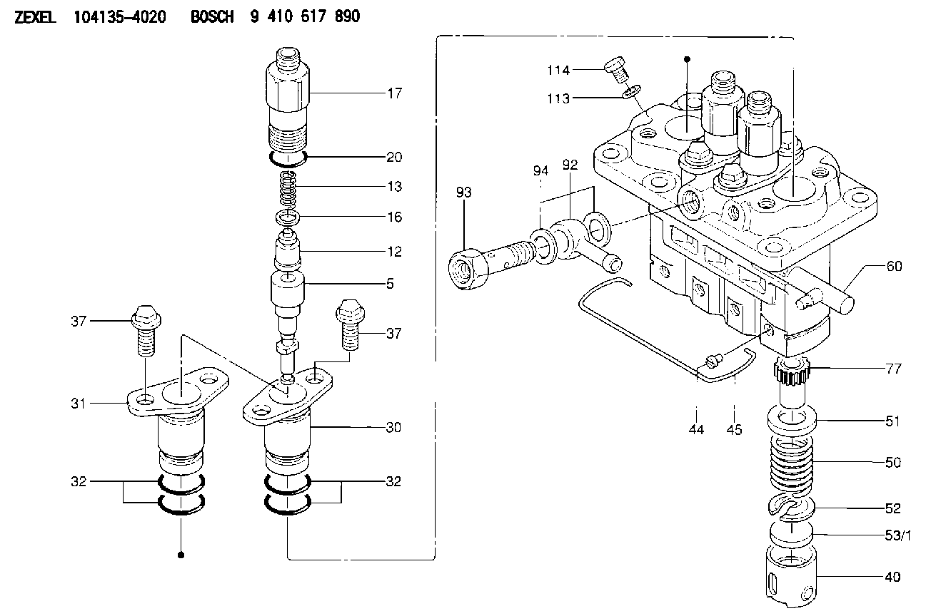
| 5. | [4] | 140163-1520 | PLUNGER-AND-BARREL ASSY |
| 12. | [4] | 140110-3620 | DELIVERY-VALVE ASSEMBLY |
| 13. | [4] | 140112-2900 | COMPRESSION SPRING |
| 16. | [4] | 140115-1400 | GASKET |
| 17. | [4] | 140116-7520 | FITTING |
| 20. | [4] | 016500-1520 | O-RING |
| 30. | [3] | 140131-0521 | FLANGE BUSHING |
| 31. | [1] | 140131-1021 | FLANGE BUSHING |
| 32. | [8] | 016550-1920 | O-RING |
| 32. | [8] | 016550-1920 | O-RING |
| 37. | [8] | 140124-0200 | BLEEDER SCREW |
| 37. | [8] | 140124-0200 | BLEEDER SCREW |
| 40. | [4] | 140200-2620 | TAPPET |
| 44. | [4] | 140212-0300 | BEARING PIN |
| 45. | [1] | 140213-1500 | LOCKING WASHER |
| 50. | [4] | 140215-1900 | COMPRESSION SPRING |
| 51. | [4] | 140216-0800 | SLOTTED WASHER |
| 52. | [4] | 140217-2200 | SLOTTED WASHER |
| 53/1. | [1] | 140217-5000 | PLATE D19T2.60 |
| 53/1. | [1] | 140217-5100 | PLATE D19T2.65 |
| 53/1. | [1] | 140217-5200 | PLATE D19T2.70 |
| 53/1. | [1] | 140217-5300 | PLATE D19T2.75 |
| 53/1. | [1] | 140217-5400 | PLATE D19T2.80 |
| 53/1. | [1] | 140217-5500 | PLATE D19T2.85 |
| 53/1. | [1] | 140217-5600 | PLATE D19T2.90 |
| 53/1. | [1] | 140217-5700 | PLATE D19T2.95 |
| 53/1. | [1] | 140217-5800 | PLATE D19T3.00 |
| 53/1. | [1] | 140217-5900 | PLATE D19T3.05 |
| 53/1. | [1] | 140217-6000 | PLATE D19T3.10 |
| 53/1. | [1] | 140217-6100 | PLATE D19T3.15 |
| 53/1. | [1] | 140217-6200 | PLATE D19T3.20 |
| 53/1. | [1] | 140217-6300 | PLATE D19T3.25 |
| 53/1. | [1] | 140217-6400 | PLATE D19T3.30 |
| 53/1. | [1] | 140217-6500 | PLATE D19T3.35 |
| 53/1. | [1] | 140217-6600 | PLATE D19T3.40 |
| 53/1. | [1] | 140217-6700 | PLATE D19T3.45 |
| 53/1. | [1] | 140217-6800 | PLATE D19T3.50 |
| 53/1. | [1] | 140217-6900 | PLATE D19T3.55 |
| 53/1. | [1] | 140217-7000 | PLATE D19T3.60 |
| 53/1. | [1] | 140217-7100 | PLATE D19T3.65 |
| 53/1. | [1] | 140217-7200 | PLATE D19T3.70 |
| 53/1. | [1] | 140217-7300 | PLATE D19T3.75 |
| 53/1. | [1] | 140217-7400 | PLATE D19T3.80 |
| 53/1. | [1] | 140217-7500 | PLATE D19T3.85 |
| 53/1. | [1] | 140217-7600 | PLATE D19T3.90 |
| 53/1. | [1] | 140217-7700 | PLATE D19T3.95 |
| 53/1. | [1] | 140217-7800 | PLATE D19T4.00 |
| 53/1. | [1] | 140217-7900 | PLATE D19T4.05 |
| 53/1. | [1] | 140217-8000 | PLATE D19T4.10 |
| 53/1. | [1] | 140253-2000 | PLATE |
| 53/1. | [1] | 140253-2100 | PLATE |
| 53/1. | [1] | 140253-2200 | PLATE |
| 53/1. | [1] | 140253-2300 | PLATE |
| 53/1. | [1] | 140253-2400 | PLATE |
| 53/1. | [1] | 140253-2500 | PLATE |
| 53/1. | [1] | 140253-2600 | PLATE |
| 53/1. | [1] | 140253-2700 | PLATE |
| 53/1. | [1] | 140253-2800 | PLATE |
| 53/1. | [1] | 140253-2900 | PLATE |
| 53/1. | [1] | 140253-3000 | PLATE |
| 53/1. | [1] | 140253-3100 | PLATE |
| 53/1. | [1] | 140253-3200 | PLATE |
| 53/1. | [1] | 140253-3300 | PLATE |
| 53/1. | [1] | 140253-3400 | PLATE |
| 53/1. | [1] | 140253-3500 | PLATE |
| 53/1. | [1] | 140253-3600 | PLATE |
| 53/1. | [1] | 140253-3700 | PLATE |
| 53/1. | [1] | 140253-3800 | PLATE |
| 53/1. | [1] | 140253-3900 | PLATE |
| 53/1. | [1] | 140253-4000 | PLATE |
| 53/1. | [1] | 140253-4100 | PLATE |
| 53/1. | [1] | 140253-4200 | PLATE |
| 53/1. | [1] | 140253-4300 | PLATE |
| 53/1. | [1] | 140253-4400 | PLATE |
| 53/1. | [1] | 140253-4500 | PLATE |
| 53/1. | [1] | 140253-4600 | PLATE |
| 53/1. | [1] | 140253-4700 | PLATE |
| 53/1. | [1] | 140253-4800 | PLATE |
| 53/1. | [1] | 140253-4900 | PLATE |
| 60. | [1] | 140243-5620 | CONTROL RACK |
| 77. | [4] | 140241-2700 | CONTROL SLEEVE |
| 92. | [1] | 029711-2050 | INLET UNION |
| 93. | [1] | 140402-1300 | EYE BOLT |
| 94. | [2] | 026512-1540 | GASKET D15.4&12.2T1.50 |
| 113. | [1] | 026508-1240 | GASKET D11.9&8.2T1 |
| 114. | [1] | 140420-1400 | BLEEDER SCREW |
Include in #1:
106673-7530
as _
Include in #2:
104135-4020
as INJECTION-PUMP ASSEMBLY
Cross reference number
Zexel num
Bosch num
Firm num
Name
Information:
1. Remove shaft (2). Remove pin (1) from the shaft.2. Remove pins (3) from the flyweights. Remove flyweights (4). 3. Remove ring, races (6) and the bearing from riser (follower) (5). 4. Remove cover (7) and spring (8) from the governor housing. There is force on the cover from the spring.5. Remove seal (9) from the cover. 6. Remove cover (10) for the low and high idle adjustments.7. Remove locknut and screw (13) for the high idle adjustment.8. Remove bolt (15) and the washers for the low idle adjustment.9. Remove spring (16) and the guide.10. Remove pin (14) and plate (11).11. Remove shaft (12) from the housing. 12. Remove two spacers (17) and pin (18) from the shaft. 13. Remove shaft (19) from the governor housing.14. Remove washer (20) and levers (21) and (22) from the governor housing. 15. Remove seal (23) and the bearing.16. Remove seals (24) and (25) from the governor housing.Assemble Governor
1. Install the bearing and seal in the housing with tool (A). The lip of the seal must be toward the bearing. 2. Install seal (1) in housing with tool (A). The lip of the seal must be toward inside of housing.3. Install seal (2) in the housing with tool (B). The lip of the seal must be toward the inside of the housing. 4. Install shaft (3) in the housing. 5. Install plates (4), spacers (8) and pin (7) on shaft (5).6. Install shaft (5) in the housing and through washer (9) and levers (6). 7. Install pin (11) in the holes of the plates.8. Install screw (10) and the locknut for the high idle adjustment.9. Install spring (13) and the guide.10. Install bolt (12) and the washer for the low idle adjustment.11. Push plate and pin (11) over toward bolt (12) and tighten the bolt. 12. Install the seal in cover (14) with tooling (B). The lip of the seal must be toward the inside. 13. Install spring (15) in the cover. Install cover (14) on the housing.
Spring (15) must be installed with the end of the spring in the position shown.
14. Install the cover (16) for the idle adjustment screws. 15. Install bearing (19) between races (18) on riser (follower) (17). Install ring (20). Ring (20) holds the washers on the riser (follower).16. Install the pin in shaft (23). 17. Install flyweights (22) and pin (21).18. Install shaft (23) in the flyweight assembly.end by: a) connection of governor to fuel injection pump housingb) Make adjustment of fuel system setting (See Fuel System Setting in Testing and Adjusting.)