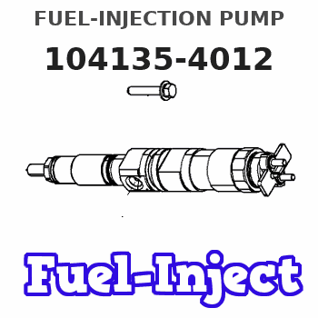
Information fuel-injection pump
BOSCH
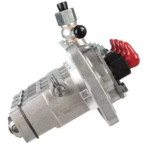
9 410 618 466
9410618466
ZEXEL
104135-4012
1041354012
ISHIKAWAJIMA-S
131017631
131017631
Rating:
Compare Prices: .
As an associate, we earn commssions on qualifying purchases through the links below

104135-4010 104135-4012 Fuel Injection Pump Compatible for Perkins 404D-22 404D-22T 404D-22TA 404C-22 404C-22T Shibaura N844 Engine Holland TC35 TC40 TC45 TC55 L160 L170 L175 L215 Tractor Loader
JPSMZSC Product Name:Fuel Injection Pump || Part number:104135-4010 104135-4012 || Application:Compatible for Perkins 404D-22 404D-22T 404D-22TA 404C-22 404C-22T Shibaura N844 Engine Holland TC35 TC40 TC45 TC55 L160 L170 L175 L215 Tractor Loader || Note: Please confirm that the product shown in the part number is what you need. If you cannot confirm, you can leave us a message and provide your engine serial number and nameplate. || Tip: We mainly deal in all parts of the construction machinery series. Our product has stable performance, fast response, high reliability, and easy installation. High quality, most guaranteed. If you have any other requirements, please contact us.
JPSMZSC Product Name:Fuel Injection Pump || Part number:104135-4010 104135-4012 || Application:Compatible for Perkins 404D-22 404D-22T 404D-22TA 404C-22 404C-22T Shibaura N844 Engine Holland TC35 TC40 TC45 TC55 L160 L170 L175 L215 Tractor Loader || Note: Please confirm that the product shown in the part number is what you need. If you cannot confirm, you can leave us a message and provide your engine serial number and nameplate. || Tip: We mainly deal in all parts of the construction machinery series. Our product has stable performance, fast response, high reliability, and easy installation. High quality, most guaranteed. If you have any other requirements, please contact us.

Nayuank Fuel Injection Pump 131017631 131017630 104135-4012 Fits For Perkins Engine 404D-22 404D-22T 404D-22TA 404C-22 404C-22T 104-22
Nayuank Part Name: Fuel Injection Pump || Part Number: 131017631 131017630 104135-4012 Note: Please check the fitment carefully before purchase. Or just tell us the part number you need. || Engine Model: 404D-22T || Applicable: Fits For Perkins Engine 404D-22 404D-22T 404D-22TA 404C-22 404C-22T 104-22 || Package included: 1pcs Fuel Injection Pump 131017631 131017630 104135-4012
Nayuank Part Name: Fuel Injection Pump || Part Number: 131017631 131017630 104135-4012 Note: Please check the fitment carefully before purchase. Or just tell us the part number you need. || Engine Model: 404D-22T || Applicable: Fits For Perkins Engine 404D-22 404D-22T 404D-22TA 404C-22 404C-22T 104-22 || Package included: 1pcs Fuel Injection Pump 131017631 131017630 104135-4012

SBA131017630 SBA131017631 131017630 131017631 Fuel Injection Pump for Perkins 404D-22 404D-22T 404C-22 Engine New Holland 3415 TC35DA TC40DA TC48DA TC55DA L160 C175 L170 L175 Case DX40 DX45 D45 D35
HIRINTOL 🔸Replace Part Number: 131017630 SBA131017630 131017631 SBA131017631 || 🔸Engine Model: for Perkins 404D-22 404D-22T 404D-22TA 404C-22 Engine; for Shibaura N844, ISM N844 Engine || 🔸Compatible Model: for Ford-New Holland Tractor: 3415, TC35D, TC45A, TC40, TC45D, TC40A, TC45DA, TC40D, TC35, TC40DA, TC35A, 2120, TC45, TC35DA, TC55DA, TC48DA, TT50A || 🔸Compatible Model: for Ford-New Holland Loader: L160, C175, L170, L175, TT45A, LS160, LS170, L215 || 🔸Durability: Made of high strength metal and composite plastic, with the best erosion resistance and service life, providing long-lasting performance and reliability.
HIRINTOL 🔸Replace Part Number: 131017630 SBA131017630 131017631 SBA131017631 || 🔸Engine Model: for Perkins 404D-22 404D-22T 404D-22TA 404C-22 Engine; for Shibaura N844, ISM N844 Engine || 🔸Compatible Model: for Ford-New Holland Tractor: 3415, TC35D, TC45A, TC40, TC45D, TC40A, TC45DA, TC40D, TC35, TC40DA, TC35A, 2120, TC45, TC35DA, TC55DA, TC48DA, TT50A || 🔸Compatible Model: for Ford-New Holland Loader: L160, C175, L170, L175, TT45A, LS160, LS170, L215 || 🔸Durability: Made of high strength metal and composite plastic, with the best erosion resistance and service life, providing long-lasting performance and reliability.
You can express buy:
USD 633.26
14-06-2025
14-06-2025
Fuel Injection Pump 1311017630 131017631 For Perkins 404D-22 404D-22T 404C-22 404C-22T 104-22 Engine Shibaura N844 Engine
USD 3737.19
02-06-2025
02-06-2025
Fuel Injection Pump 131017631 for Perkins Engine 104-22 KR KRC
Components :
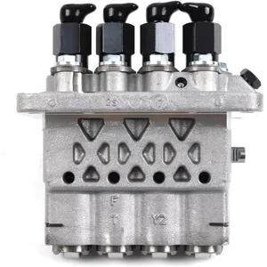
| 0. | INJECTION-PUMP ASSEMBLY | 104135-4012 |
| 1. | _ | |
| 2. | FUEL INJECTION PUMP | |
| 3. | NUMBER PLATE | |
| 4. | _ | |
| 5. | CAPSULE | |
| 6. | ADJUSTING DEVICE | |
| 7. | NOZZLE AND HOLDER ASSY | 105148-1170 |
| 8. | Nozzle and Holder | |
| 9. | Open Pre:MPa(Kqf/cm2) | 14.7(150) |
| 10. | NOZZLE-HOLDER | 105078-0100 |
| 11. | NOZZLE | 105007-1170 |
Scheme ###:
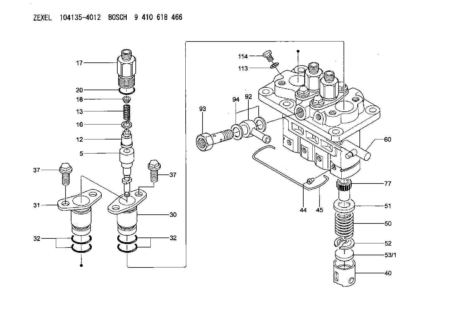
| 5. | [4] | 140153-5420 | PLUNGER-AND-BARREL ASSY |
| 12. | [4] | 140110-4320 | DELIVERY-VALVE ASSEMBLY |
| 13. | [4] | 140112-2900 | COMPRESSION SPRING |
| 16. | [4] | 140115-1400 | GASKET |
| 17. | [4] | 140116-7600 | FITTING |
| 18. | [4] | 140117-1800 | SLOTTED WASHER |
| 20. | [4] | 140118-0301 | O-RING |
| 30. | [3] | 140131-0521 | FLANGE BUSHING |
| 31. | [1] | 140131-1021 | FLANGE BUSHING |
| 32. | [8] | 140118-0201 | O-RING |
| 32. | [8] | 140118-0201 | O-RING |
| 37. | [8] | 140124-0200 | BLEEDER SCREW |
| 37. | [8] | 140124-0200 | BLEEDER SCREW |
| 40. | [4] | 140200-2620 | TAPPET |
| 44. | [4] | 140212-0300 | BEARING PIN |
| 45. | [1] | 140213-1500 | LOCKING WASHER |
| 50. | [4] | 140215-1900 | COMPRESSION SPRING |
| 51. | [4] | 140216-0800 | SLOTTED WASHER |
| 52. | [4] | 140217-2200 | SLOTTED WASHER |
| 53/1. | [1] | 140217-5000 | PLATE D19T2.60 |
| 53/1. | [1] | 140217-5100 | PLATE D19T2.65 |
| 53/1. | [1] | 140217-5200 | PLATE D19T2.70 |
| 53/1. | [1] | 140217-5300 | PLATE D19T2.75 |
| 53/1. | [1] | 140217-5400 | PLATE D19T2.80 |
| 53/1. | [1] | 140217-5500 | PLATE D19T2.85 |
| 53/1. | [1] | 140217-5600 | PLATE D19T2.90 |
| 53/1. | [1] | 140217-5700 | PLATE D19T2.95 |
| 53/1. | [1] | 140217-5800 | PLATE D19T3.00 |
| 53/1. | [1] | 140217-5900 | PLATE D19T3.05 |
| 53/1. | [1] | 140217-6000 | PLATE D19T3.10 |
| 53/1. | [1] | 140217-6100 | PLATE D19T3.15 |
| 53/1. | [1] | 140217-6200 | PLATE D19T3.20 |
| 53/1. | [1] | 140217-6300 | PLATE D19T3.25 |
| 53/1. | [1] | 140217-6400 | PLATE D19T3.30 |
| 53/1. | [1] | 140217-6500 | PLATE D19T3.35 |
| 53/1. | [1] | 140217-6600 | PLATE D19T3.40 |
| 53/1. | [1] | 140217-6700 | PLATE D19T3.45 |
| 53/1. | [1] | 140217-6800 | PLATE D19T3.50 |
| 53/1. | [1] | 140217-6900 | PLATE D19T3.55 |
| 53/1. | [1] | 140217-7000 | PLATE D19T3.60 |
| 53/1. | [1] | 140217-7100 | PLATE D19T3.65 |
| 53/1. | [1] | 140217-7200 | PLATE D19T3.70 |
| 53/1. | [1] | 140217-7300 | PLATE D19T3.75 |
| 53/1. | [1] | 140217-7400 | PLATE D19T3.80 |
| 53/1. | [1] | 140217-7500 | PLATE D19T3.85 |
| 53/1. | [1] | 140217-7600 | PLATE D19T3.90 |
| 53/1. | [1] | 140217-7700 | PLATE D19T3.95 |
| 53/1. | [1] | 140217-7800 | PLATE D19T4.00 |
| 53/1. | [1] | 140217-7900 | PLATE D19T4.05 |
| 53/1. | [1] | 140217-8000 | PLATE D19T4.10 |
| 53/1. | [1] | 140253-2000 | PLATE |
| 53/1. | [1] | 140253-2100 | PLATE |
| 53/1. | [1] | 140253-2200 | PLATE |
| 53/1. | [1] | 140253-2300 | PLATE |
| 53/1. | [1] | 140253-2400 | PLATE |
| 53/1. | [1] | 140253-2500 | PLATE |
| 53/1. | [1] | 140253-2600 | PLATE |
| 53/1. | [1] | 140253-2700 | PLATE |
| 53/1. | [1] | 140253-2800 | PLATE |
| 53/1. | [1] | 140253-2900 | PLATE |
| 53/1. | [1] | 140253-3000 | PLATE |
| 53/1. | [1] | 140253-3100 | PLATE |
| 53/1. | [1] | 140253-3200 | PLATE |
| 53/1. | [1] | 140253-3300 | PLATE |
| 53/1. | [1] | 140253-3400 | PLATE |
| 53/1. | [1] | 140253-3500 | PLATE |
| 53/1. | [1] | 140253-3600 | PLATE |
| 53/1. | [1] | 140253-3700 | PLATE |
| 53/1. | [1] | 140253-3800 | PLATE |
| 53/1. | [1] | 140253-3900 | PLATE |
| 53/1. | [1] | 140253-4000 | PLATE |
| 53/1. | [1] | 140253-4100 | PLATE |
| 53/1. | [1] | 140253-4200 | PLATE |
| 53/1. | [1] | 140253-4300 | PLATE |
| 53/1. | [1] | 140253-4400 | PLATE |
| 53/1. | [1] | 140253-4500 | PLATE |
| 53/1. | [1] | 140253-4600 | PLATE |
| 53/1. | [1] | 140253-4700 | PLATE |
| 53/1. | [1] | 140253-4800 | PLATE |
| 53/1. | [1] | 140253-4900 | PLATE |
| 60. | [1] | 140243-5620 | CONTROL RACK |
| 77. | [4] | 140241-2700 | CONTROL SLEEVE |
| 92. | [1] | 029711-2050 | INLET UNION |
| 93. | [1] | 140402-1300 | EYE BOLT |
| 94. | [2] | 026512-1540 | GASKET D15.4&12.2T1.50 |
| 113. | [1] | 026508-1240 | GASKET D11.9&8.2T1 |
| 114. | [1] | 140420-1400 | BLEEDER SCREW |
Include in #1:
106673-7520
as _
Include in #2:
104135-4012
as INJECTION-PUMP ASSEMBLY
Cross reference number
Zexel num
Bosch num
Firm num
Name
104135-4012
131017631 ISHIKAWAJIMA-S
FUEL-INJECTION PUMP
A K 23AD FUEL INJECTION PUMP PFR-4KX PFR
A K 23AD FUEL INJECTION PUMP PFR-4KX PFR
Information:
start by: a) remove fuel injection pump housing and governor1. Put the fuel injection pump housing on tool (A). 2. Remove bolts (1). 3. Remove bolt (2). Remove adapter housing (3) from the pump housing. 4. Remove bolts (4) and (5). Loosen bolt (6). 5. Remove governor housing (7) from the pump housing. 6. Remove spring (12), wave washer (11) and guide (10). Remove seat (8) and over fueling spring (9). 7. Pull shaft (13) up and remove it. Remove lever (14) from the housing. 8. Remove riser (follower) (17) from the shaft. Remove ring (15) and lever (16). 9. Remove cover (18) with tool (B). Tool (B) can cause damage to the cover. Always inspect the cover and install a new cover if needed.10. Install the timing pin to prevent the camshaft from turning. 11. Remove three bolts (19) that hold the flyweight assembly to the camshaft. Remove the flyweight assembly from the pump housing.12. Remove the timing pin.Connection Of Governor To Fuel Injection Pump Housing
1. Put the fuel injection pump housing on tool (A).2. Install the timing pin to prevent the camshaft from turning. 3. Put flyweight assembly (1) in position on the camshaft.
Be sure pin (2) that holds the shaft is in the correct position on back of the flyweight assembly.
4. Install new bolts for the flyweight assembly. The bolts for the flyweight assembly have a locking material on the threads and must not be used more than one time. 5. Install the cover over the flyweight assembly with tool (B). 6. Grind a taper on the bottom edge of a 1/8" screwdriver (3). Install the screwdriver through the bolt hole in the governor housing. The screwdriver must fit evenly against the flyweight assembly cover. Make a mark (stake) in four places around the cover in line with the groove in the camshaft.
Never install a used flyweight cover that is bent.
7. Install lever (4) on the dowel. Install ring (5). 8. Put riser (follower) (6) in position between the flyweights. Lift the flyweight up with a piece of wire and push the riser (follower) forward. 9. Put lever (10) in position. Lever (10) will be in the correct position when the lever end is in the groove of riser (follower) (6) and the ball end is engaged in sleeve shaft lever (9).
If lever (10) is not installed correctly, the governor can not operate and can cause the engine to over speed.
10. Install O-ring (7). Install shaft (8) to hold lever (10) in place. 11. Install over fueling spring (12) and seat (11) on the shaft. 12. Install guide (13), (wave) washer (14) and spring (15) in the governor housing.13. Put the governor housing on the fuel injection pump housing and install the bolts.end by: a) install adapter housing and leversb) install fuel injection pump housing and governorc) make adjustment of fuel system setting (See Fuel System Setting in Testing and Adjusting)