Information fuel-injection pump
BOSCH
9 410 617 059
9410617059
ZEXEL
104135-4010
1041354010
Rating:
Compare Prices: .
As an associate, we earn commssions on qualifying purchases through the links below

Fuel Injection Pump SBA131017630 SBA131017740 SBA131017800 Fikowjs Compatible for 844 Engine for Tractor 3415 TC48DA TC55DA
Fikowjs TIP: Please purchase according to the old part number, appearance is not able to judge the accuracy of the product. || Product Name:Fuel Injection Pump || Product Number:104135-4010 104135-4012 104135-4020 104135-4030 104135-4031 104135-4032 104135-4061 1041354010 1041354012 1041354020 1041354030 1041354031 1041354032 1041354061 SBA131017630 SBA131017740 SBA131017741 SBA131017800 SBA131017801 9410617059 9410618466 9410617890 9410617920 9410618362 9410618468 9410618469 || Application: Compatible for 844 Engine Compatible for 3415 TC48DA TC55DA Tractor || NOTE: There are many kinds of products in Fikowjs parts, if you can't find the part number you need, please consult us, we will reply soon!
Fikowjs TIP: Please purchase according to the old part number, appearance is not able to judge the accuracy of the product. || Product Name:Fuel Injection Pump || Product Number:104135-4010 104135-4012 104135-4020 104135-4030 104135-4031 104135-4032 104135-4061 1041354010 1041354012 1041354020 1041354030 1041354031 1041354032 1041354061 SBA131017630 SBA131017740 SBA131017741 SBA131017800 SBA131017801 9410617059 9410618466 9410617890 9410617920 9410618362 9410618468 9410618469 || Application: Compatible for 844 Engine Compatible for 3415 TC48DA TC55DA Tractor || NOTE: There are many kinds of products in Fikowjs parts, if you can't find the part number you need, please consult us, we will reply soon!

Fuel Injection Pump 104135-4010 Compatible with 844 Engine for Holland Tractor 3415 TC48DA TC55DA
Starhycfa Product name:Fuel Injection Pump || Part Number:104135-4010 1041354010 || APPlication:Compatible with 844 Engine for Holland Tractor 3415 TC48DA TC55DA || 1.Please carefully compare the pictures or OE numbers to match your original parts beCompatible withe purchasing the product. || 2.Please make sure that the model number, part number and photo is the same as yours beCompatible withe order. To Avoid placing wrong orders and wasting your precious time.
Starhycfa Product name:Fuel Injection Pump || Part Number:104135-4010 1041354010 || APPlication:Compatible with 844 Engine for Holland Tractor 3415 TC48DA TC55DA || 1.Please carefully compare the pictures or OE numbers to match your original parts beCompatible withe purchasing the product. || 2.Please make sure that the model number, part number and photo is the same as yours beCompatible withe order. To Avoid placing wrong orders and wasting your precious time.

IMELBUFF SBA131017630 131017630 104135-4010 Fuel Injection Pump for Shibaura N844 Engine Ford New Holland 3415 TC48DA TC55DA Tractor JCB 8052 Excavator
IMELBUFF 🚜Part Number: SBA131017630 131017630 104135-4010 || 🚜Engine Model: for Shibaura N844 Engine || 🚜Vehicle Application: for Ford New Holland Tractors 3415 TC48DA TC55DA; JCB 8052 Excavator || 🚜Warm Tips: If you are not sure that the pump is suitable for your vehicle, please send us email with your vehicle engine model and fuel pump part number || 🚜Service: 6-months-warranty and 24 hour support for customer service. Please feel free to contact us by email if you have any question with the product
IMELBUFF 🚜Part Number: SBA131017630 131017630 104135-4010 || 🚜Engine Model: for Shibaura N844 Engine || 🚜Vehicle Application: for Ford New Holland Tractors 3415 TC48DA TC55DA; JCB 8052 Excavator || 🚜Warm Tips: If you are not sure that the pump is suitable for your vehicle, please send us email with your vehicle engine model and fuel pump part number || 🚜Service: 6-months-warranty and 24 hour support for customer service. Please feel free to contact us by email if you have any question with the product
Components :
| 0. | INJECTION-PUMP ASSEMBLY | 104135-4010 |
| 1. | _ | |
| 2. | FUEL INJECTION PUMP | |
| 3. | NUMBER PLATE | |
| 4. | _ | |
| 5. | CAPSULE | |
| 6. | ADJUSTING DEVICE | |
| 7. | NOZZLE AND HOLDER ASSY | 105141-2200 |
| 8. | Nozzle and Holder | |
| 9. | Open Pre:MPa(Kqf/cm2) | 11.8{120} |
| 10. | NOZZLE-HOLDER | 105071-0640 |
| 11. | NOZZLE | 105000-1010 |
Scheme ###:
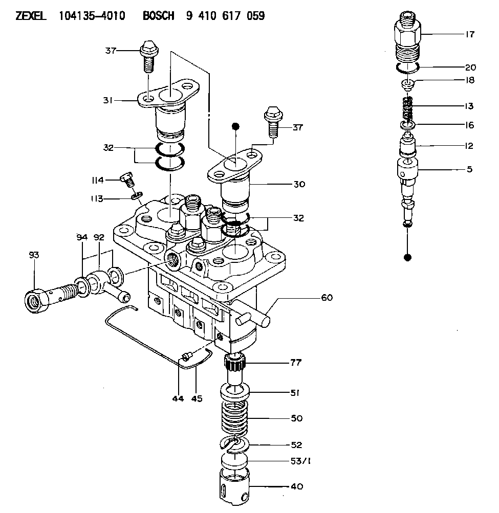
| 5. | [4] | 140153-5420 | PLUNGER-AND-BARREL ASSY |
| 12. | [4] | 140110-4320 | DELIVERY-VALVE ASSEMBLY |
| 13. | [4] | 140112-2900 | COMPRESSION SPRING |
| 16. | [4] | 140115-1400 | GASKET |
| 17. | [4] | 140116-7600 | FITTING |
| 18. | [4] | 140117-1800 | SLOTTED WASHER |
| 20. | [4] | 016500-1520 | O-RING |
| 30. | [3] | 140131-0521 | FLANGE BUSHING |
| 31. | [1] | 140131-1021 | FLANGE BUSHING |
| 32. | [8] | 016550-1920 | O-RING |
| 32. | [8] | 016550-1920 | O-RING |
| 37. | [8] | 140124-0200 | BLEEDER SCREW |
| 37. | [8] | 140124-0200 | BLEEDER SCREW |
| 40. | [4] | 140200-2620 | TAPPET |
| 44. | [4] | 140212-0300 | BEARING PIN |
| 45. | [1] | 140213-1500 | LOCKING WASHER |
| 50. | [4] | 140215-1900 | COMPRESSION SPRING |
| 51. | [4] | 140216-0800 | SLOTTED WASHER |
| 52. | [4] | 140217-2200 | SLOTTED WASHER |
| 53/1. | [1] | 140217-5000 | PLATE D19T2.60 |
| 53/1. | [1] | 140217-5100 | PLATE D19T2.65 |
| 53/1. | [1] | 140217-5200 | PLATE D19T2.70 |
| 53/1. | [1] | 140217-5300 | PLATE D19T2.75 |
| 53/1. | [1] | 140217-5400 | PLATE D19T2.80 |
| 53/1. | [1] | 140217-5500 | PLATE D19T2.85 |
| 53/1. | [1] | 140217-5600 | PLATE D19T2.90 |
| 53/1. | [1] | 140217-5700 | PLATE D19T2.95 |
| 53/1. | [1] | 140217-5800 | PLATE D19T3.00 |
| 53/1. | [1] | 140217-5900 | PLATE D19T3.05 |
| 53/1. | [1] | 140217-6000 | PLATE D19T3.10 |
| 53/1. | [1] | 140217-6100 | PLATE D19T3.15 |
| 53/1. | [1] | 140217-6200 | PLATE D19T3.20 |
| 53/1. | [1] | 140217-6300 | PLATE D19T3.25 |
| 53/1. | [1] | 140217-6400 | PLATE D19T3.30 |
| 53/1. | [1] | 140217-6500 | PLATE D19T3.35 |
| 53/1. | [1] | 140217-6600 | PLATE D19T3.40 |
| 53/1. | [1] | 140217-6700 | PLATE D19T3.45 |
| 53/1. | [1] | 140217-6800 | PLATE D19T3.50 |
| 53/1. | [1] | 140217-6900 | PLATE D19T3.55 |
| 53/1. | [1] | 140217-7000 | PLATE D19T3.60 |
| 53/1. | [1] | 140217-7100 | PLATE D19T3.65 |
| 53/1. | [1] | 140217-7200 | PLATE D19T3.70 |
| 53/1. | [1] | 140217-7300 | PLATE D19T3.75 |
| 53/1. | [1] | 140217-7400 | PLATE D19T3.80 |
| 53/1. | [1] | 140217-7500 | PLATE D19T3.85 |
| 53/1. | [1] | 140217-7600 | PLATE D19T3.90 |
| 53/1. | [1] | 140217-7700 | PLATE D19T3.95 |
| 53/1. | [1] | 140217-7800 | PLATE D19T4.00 |
| 53/1. | [1] | 140217-7900 | PLATE D19T4.05 |
| 53/1. | [1] | 140217-8000 | PLATE D19T4.10 |
| 53/1. | [1] | 140253-2000 | PLATE |
| 53/1. | [1] | 140253-2100 | PLATE |
| 53/1. | [1] | 140253-2200 | PLATE |
| 53/1. | [1] | 140253-2300 | PLATE |
| 53/1. | [1] | 140253-2400 | PLATE |
| 53/1. | [1] | 140253-2500 | PLATE |
| 53/1. | [1] | 140253-2600 | PLATE |
| 53/1. | [1] | 140253-2700 | PLATE |
| 53/1. | [1] | 140253-2800 | PLATE |
| 53/1. | [1] | 140253-2900 | PLATE |
| 53/1. | [1] | 140253-3000 | PLATE |
| 53/1. | [1] | 140253-3100 | PLATE |
| 53/1. | [1] | 140253-3200 | PLATE |
| 53/1. | [1] | 140253-3300 | PLATE |
| 53/1. | [1] | 140253-3400 | PLATE |
| 53/1. | [1] | 140253-3500 | PLATE |
| 53/1. | [1] | 140253-3600 | PLATE |
| 53/1. | [1] | 140253-3700 | PLATE |
| 53/1. | [1] | 140253-3800 | PLATE |
| 53/1. | [1] | 140253-3900 | PLATE |
| 53/1. | [1] | 140253-4000 | PLATE |
| 53/1. | [1] | 140253-4100 | PLATE |
| 53/1. | [1] | 140253-4200 | PLATE |
| 53/1. | [1] | 140253-4300 | PLATE |
| 53/1. | [1] | 140253-4400 | PLATE |
| 53/1. | [1] | 140253-4500 | PLATE |
| 53/1. | [1] | 140253-4600 | PLATE |
| 53/1. | [1] | 140253-4700 | PLATE |
| 53/1. | [1] | 140253-4800 | PLATE |
| 53/1. | [1] | 140253-4900 | PLATE |
| 60. | [1] | 140243-5620 | CONTROL RACK |
| 77. | [4] | 140241-2700 | CONTROL SLEEVE |
| 92. | [1] | 029711-2050 | INLET UNION |
| 93. | [1] | 140402-1300 | EYE BOLT |
| 94. | [2] | 026512-1540 | GASKET D15.4&12.2T1.50 |
| 113. | [1] | 026508-1240 | GASKET D11.9&8.2T1 |
| 114. | [1] | 140420-1400 | BLEEDER SCREW |
Include in #1:
106673-7550
as _
Include in #2:
104135-4010
as INJECTION-PUMP ASSEMBLY
Cross reference number
Zexel num
Bosch num
Firm num
Name
Information:
start by: a) remove fuel injection lines 1. Remove cover (1) from the front of the timing gear cover. Remove bolt (2) and washer (3). Install bolt (2) again to the position shown. Use tool (A) to loosen the pump drive gear from the camshaft. Remove tool (A) and bolt (2).2. Remove the governor linkage. Disconnect the fuel supply line. 3. Remove inlet oil tube (4) for the turbocharger.4. Disconnect the air tube from the fuel ratio control.5. Disconnect hose (5).6. Disconnect the three drain tubes from the fuel injection pump housing.7. Remove bracket (6).8. Remove the three nuts that hold the fuel injection pump housing and governor to the timing plate.9. Remove the fuel injection pump housing and governor.Install Fuel Injection Pump Housing And Governor
1. Use the following procedures to put the No. 1 piston at top center on the compression stroke. No. 1 piston at top center (TC) on the compression stroke is the starting point for all timing procedures. The engine is seen from the flywheel end when direction of flywheel rotation is given.a) Turn the flywheel approximately 30 degrees clockwise. The reason for making this step is to be sure the play is removed from the timing gears when the engine is put on top center. b) For engines with a timing pointer, remove the cover on the flywheel housing. Turn the flywheel counterclockwise until the "TC 1" mark on the flywheel is in alignment with the pointer.c) For engines with a timing bolt, turn the flywheel counterclockwise until a 3/8-16 NC bolt can be installed in the flywheel through the hole in the flywheel housing. Do not turn the flywheel backwards.d) Remove the breather from the valve cover. The rocker arms for No. 1 piston can be seen through the breather hole in the valve cover.e) Check to see if both rocker arms for the No. 1 piston can be moved backward and forward by hand. The No. 1 piston is at top center on the compression stroke when the "TC 1" mark on the flywheel is in alignment with the pointer, or the bolt can be put in the flywheel through the hole in the flywheel housing, and both rocker arms for the No. 1 piston can be moved backward and forward by hand. f) If both rocker arms can not be moved by hand, the No. 1 piston is not at top center on the compression stroke. Turn the flywheel counterclockwise one full turn (360°). For engines with a timing pointer, the "TC 1" mark on the flywheel must then be in alignment with the pointer. For engines with a timing bolt, the bolt must be installed in the flywheel through the hole in the flywheel housing.2. For engines with a timing pointer, turn the flywheel counterclockwise until the pointer is between the 1° and 2° mark on the flywheel as shown. 3. For engines with a timing bolt, do not turn the flywheel past this position. 4. Remove the
1. Use the following procedures to put the No. 1 piston at top center on the compression stroke. No. 1 piston at top center (TC) on the compression stroke is the starting point for all timing procedures. The engine is seen from the flywheel end when direction of flywheel rotation is given.a) Turn the flywheel approximately 30 degrees clockwise. The reason for making this step is to be sure the play is removed from the timing gears when the engine is put on top center. b) For engines with a timing pointer, remove the cover on the flywheel housing. Turn the flywheel counterclockwise until the "TC 1" mark on the flywheel is in alignment with the pointer.c) For engines with a timing bolt, turn the flywheel counterclockwise until a 3/8-16 NC bolt can be installed in the flywheel through the hole in the flywheel housing. Do not turn the flywheel backwards.d) Remove the breather from the valve cover. The rocker arms for No. 1 piston can be seen through the breather hole in the valve cover.e) Check to see if both rocker arms for the No. 1 piston can be moved backward and forward by hand. The No. 1 piston is at top center on the compression stroke when the "TC 1" mark on the flywheel is in alignment with the pointer, or the bolt can be put in the flywheel through the hole in the flywheel housing, and both rocker arms for the No. 1 piston can be moved backward and forward by hand. f) If both rocker arms can not be moved by hand, the No. 1 piston is not at top center on the compression stroke. Turn the flywheel counterclockwise one full turn (360°). For engines with a timing pointer, the "TC 1" mark on the flywheel must then be in alignment with the pointer. For engines with a timing bolt, the bolt must be installed in the flywheel through the hole in the flywheel housing.2. For engines with a timing pointer, turn the flywheel counterclockwise until the pointer is between the 1° and 2° mark on the flywheel as shown. 3. For engines with a timing bolt, do not turn the flywheel past this position. 4. Remove the