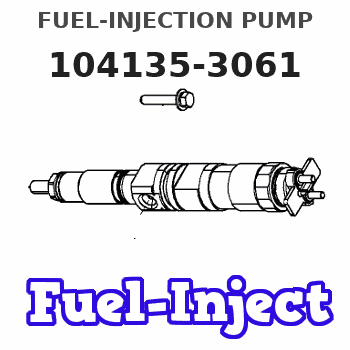
Information fuel-injection pump
BOSCH
9 410 618 465
9410618465
ZEXEL
104135-3061
1041353061
ISHIKAWAJIMA-S
131017811
131017811
Rating:
Compare Prices: .
As an associate, we earn commssions on qualifying purchases through the links below

SBA131017811 131017811 104134-3061 Fuel Injection Pump Compatible For New Holland Loader L140 L150 LS140 LS150 Case Tractor DX31 DX34 DX35
SDETASOQ Precise control: precise fuel injection, optimized combustion efficiency, reduced fuel consumption, and improved engine power output || Long lifespan and low maintenance: using high-strength wear-resistant alloy materials and corrosion-resistant coatings to reduce maintenance costs and downtime || Stable operation under all operating conditions: tested in extreme environments, continuously stable, and adaptable to various complex road and climate conditions || Silent and efficient operation: Adopting a noise reduction structure, it can maintain quietness even during high-speed operation, without interfering with the driving experience || SBA131017811 131017811 104134-3061 Fuel Injection Pump Compatible For New Holland Loader L140 L150 LS140 LS150 Case Tractor DX31 DX34 DX35
SDETASOQ Precise control: precise fuel injection, optimized combustion efficiency, reduced fuel consumption, and improved engine power output || Long lifespan and low maintenance: using high-strength wear-resistant alloy materials and corrosion-resistant coatings to reduce maintenance costs and downtime || Stable operation under all operating conditions: tested in extreme environments, continuously stable, and adaptable to various complex road and climate conditions || Silent and efficient operation: Adopting a noise reduction structure, it can maintain quietness even during high-speed operation, without interfering with the driving experience || SBA131017811 131017811 104134-3061 Fuel Injection Pump Compatible For New Holland Loader L140 L150 LS140 LS150 Case Tractor DX31 DX34 DX35

Fuel Injection Pump 131017811 104135-3061 for Shibaura Engine N843 New Holland G6030 G6035 BOOMER 2030 2035 T1510 T2220
DIGERTECH Part number:131017811 || Application: for Shibaura Engine N843 New Holland G6030 G6035 BOOMER 2030 2035 T1510 T2220
DIGERTECH Part number:131017811 || Application: for Shibaura Engine N843 New Holland G6030 G6035 BOOMER 2030 2035 T1510 T2220

Fuel Injection Pump Compatible For Kubota New Holland TC34 TC31 131017811 104134-3061 9410618465 1041343061 Engine Replacement Parts
TBEFQVAW Lightweight design: effectively reduces vehicle load, improves fuel economy, and facilitates installation and handling || Multi specification adaptation: providing multiple flow specifications and models to meet the needs of different displacement engines || Adaptive installation: Standardized interface design, compatible with 95% of mainstream engine models, no need for complex modifications || Anti corrosion coating: The surface of key components is covered with anti-corrosion coating, which is not afraid of humid coastal environments and harsh weather conditions || Fuel Injection Pump Compatible For Kubota New Holland TC34 TC31 131017811 104134-3061 9410618465 1041343061 Engine Replacement Parts
TBEFQVAW Lightweight design: effectively reduces vehicle load, improves fuel economy, and facilitates installation and handling || Multi specification adaptation: providing multiple flow specifications and models to meet the needs of different displacement engines || Adaptive installation: Standardized interface design, compatible with 95% of mainstream engine models, no need for complex modifications || Anti corrosion coating: The surface of key components is covered with anti-corrosion coating, which is not afraid of humid coastal environments and harsh weather conditions || Fuel Injection Pump Compatible For Kubota New Holland TC34 TC31 131017811 104134-3061 9410618465 1041343061 Engine Replacement Parts
You can express buy:
USD 450
19-05-2025
19-05-2025
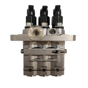
104135-3061 131017811 Fuel Injection Pump for New Holland tractor 2030 2035 DX35 DX31 DX34 parts 53061 Diesel Injector Pump
USD 450
19-05-2025
19-05-2025
New 403D-15 Diesel Engine Pump Head 104135-3061 Perkins Fuel Injection Pump for Construction Machinery Parts
Images:
USD 581.35

[19-May-2025]
USD 1010.67

[19-May-2025]
USD 351

[01-Jul-2025]
USD 1007.76

[14-Jun-2025]
Components :
| 0. | INJECTION-PUMP ASSEMBLY | 104135-3061 |
| 1. | _ | |
| 2. | FUEL INJECTION PUMP | |
| 3. | NUMBER PLATE | |
| 4. | _ | |
| 5. | CAPSULE | |
| 6. | ADJUSTING DEVICE | |
| 7. | NOZZLE AND HOLDER ASSY | 105148-1170 |
| 8. | Nozzle and Holder | |
| 9. | Open Pre:MPa(Kqf/cm2) | 14.7(150) |
| 10. | NOZZLE-HOLDER | 105078-0100 |
| 11. | NOZZLE | 105007-1170 |
Scheme ###:
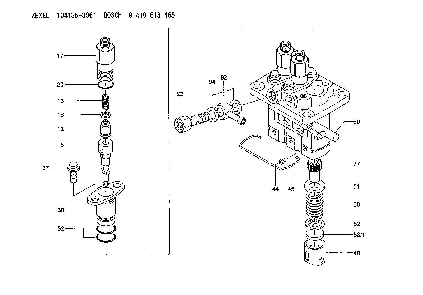
| 5. | [3] | 140163-2020 | PLUNGER-AND-BARREL ASSY |
| 12. | [3] | 140110-3620 | DELIVERY-VALVE ASSEMBLY |
| 13. | [3] | 140112-2900 | COMPRESSION SPRING |
| 16. | [3] | 140115-1400 | GASKET |
| 17. | [3] | 140116-7520 | FITTING |
| 20. | [3] | 140118-0301 | O-RING |
| 30. | [3] | 140131-0521 | FLANGE BUSHING |
| 32. | [6] | 140118-0201 | O-RING |
| 37. | [6] | 140124-0200 | BLEEDER SCREW |
| 40. | [3] | 140200-2620 | TAPPET |
| 44. | [3] | 140212-0300 | BEARING PIN |
| 45. | [1] | 140213-1400 | LOCKING WASHER |
| 50. | [3] | 140215-1900 | COMPRESSION SPRING |
| 51. | [3] | 140216-0800 | SLOTTED WASHER |
| 52. | [3] | 140217-2200 | SLOTTED WASHER |
| 53/1. | [1] | 140217-5000 | PLATE D19T2.60 |
| 53/1. | [1] | 140217-5100 | PLATE D19T2.65 |
| 53/1. | [1] | 140217-5200 | PLATE D19T2.70 |
| 53/1. | [1] | 140217-5300 | PLATE D19T2.75 |
| 53/1. | [1] | 140217-5400 | PLATE D19T2.80 |
| 53/1. | [1] | 140217-5500 | PLATE D19T2.85 |
| 53/1. | [1] | 140217-5600 | PLATE D19T2.90 |
| 53/1. | [1] | 140217-5700 | PLATE D19T2.95 |
| 53/1. | [1] | 140217-5800 | PLATE D19T3.00 |
| 53/1. | [1] | 140217-5900 | PLATE D19T3.05 |
| 53/1. | [1] | 140217-6000 | PLATE D19T3.10 |
| 53/1. | [1] | 140217-6100 | PLATE D19T3.15 |
| 53/1. | [1] | 140217-6200 | PLATE D19T3.20 |
| 53/1. | [1] | 140217-6300 | PLATE D19T3.25 |
| 53/1. | [1] | 140217-6400 | PLATE D19T3.30 |
| 53/1. | [1] | 140217-6500 | PLATE D19T3.35 |
| 53/1. | [1] | 140217-6600 | PLATE D19T3.40 |
| 53/1. | [1] | 140217-6700 | PLATE D19T3.45 |
| 53/1. | [1] | 140217-6800 | PLATE D19T3.50 |
| 53/1. | [1] | 140217-6900 | PLATE D19T3.55 |
| 53/1. | [1] | 140217-7000 | PLATE D19T3.60 |
| 53/1. | [1] | 140217-7100 | PLATE D19T3.65 |
| 53/1. | [1] | 140217-7200 | PLATE D19T3.70 |
| 53/1. | [1] | 140217-7300 | PLATE D19T3.75 |
| 53/1. | [1] | 140217-7400 | PLATE D19T3.80 |
| 53/1. | [1] | 140217-7500 | PLATE D19T3.85 |
| 53/1. | [1] | 140217-7600 | PLATE D19T3.90 |
| 53/1. | [1] | 140217-7700 | PLATE D19T3.95 |
| 53/1. | [1] | 140217-7800 | PLATE D19T4.00 |
| 53/1. | [1] | 140217-7900 | PLATE D19T4.05 |
| 53/1. | [1] | 140217-8000 | PLATE D19T4.10 |
| 53/1. | [1] | 140253-2000 | PLATE |
| 53/1. | [1] | 140253-2100 | PLATE |
| 53/1. | [1] | 140253-2200 | PLATE |
| 53/1. | [1] | 140253-2300 | PLATE |
| 53/1. | [1] | 140253-2400 | PLATE |
| 53/1. | [1] | 140253-2500 | PLATE |
| 53/1. | [1] | 140253-2600 | PLATE |
| 53/1. | [1] | 140253-2700 | PLATE |
| 53/1. | [1] | 140253-2800 | PLATE |
| 53/1. | [1] | 140253-2900 | PLATE |
| 53/1. | [1] | 140253-3000 | PLATE |
| 53/1. | [1] | 140253-3100 | PLATE |
| 53/1. | [1] | 140253-3200 | PLATE |
| 53/1. | [1] | 140253-3300 | PLATE |
| 53/1. | [1] | 140253-3400 | PLATE |
| 53/1. | [1] | 140253-3500 | PLATE |
| 53/1. | [1] | 140253-3600 | PLATE |
| 53/1. | [1] | 140253-3700 | PLATE |
| 53/1. | [1] | 140253-3800 | PLATE |
| 53/1. | [1] | 140253-3900 | PLATE |
| 53/1. | [1] | 140253-4000 | PLATE |
| 53/1. | [1] | 140253-4100 | PLATE |
| 53/1. | [1] | 140253-4200 | PLATE |
| 53/1. | [1] | 140253-4300 | PLATE |
| 53/1. | [1] | 140253-4400 | PLATE |
| 53/1. | [1] | 140253-4500 | PLATE |
| 53/1. | [1] | 140253-4600 | PLATE |
| 53/1. | [1] | 140253-4700 | PLATE |
| 53/1. | [1] | 140253-4800 | PLATE |
| 53/1. | [1] | 140253-4900 | PLATE |
| 60. | [1] | 140243-5520 | CONTROL RACK |
| 77. | [3] | 140241-2700 | CONTROL SLEEVE |
| 92. | [1] | 029711-2050 | INLET UNION |
| 93. | [1] | 140402-1300 | EYE BOLT |
| 94. | [2] | 026512-1540 | GASKET D15.4&12.2T1.50 |
Include in #2:
104135-3061
as INJECTION-PUMP ASSEMBLY
Cross reference number
Zexel num
Bosch num
Firm num
Name
Information:
Engine Runs Smoothly Recommended Procedure1. Engine Used in a Lug Condition ... "Lugging" (when the truck is used in a gear too high for engine rpm to go up as accelerator pedal is pushed farther down, or when the truck is used in a gear where engine rpm goes down with accelerator pedal at maximum travel) the engine causes a reduction in the intake of air with full fuel delivery to the cylinders. Because there is not enough air to burn all the fuel, the fuel that is not used comes out the exhaust as black smoke. To prevent lugging the engine, use a gear where engine can have "acceleration" (increase in speed) under load.2. Dirty Air Cleaner ... If the air cleaner has a restriction indicator, see if the red piston is in view. If there is no restriction indicator, restriction can be checked with a water manometer or a vacuum gauge (which measures in inches of water). Make a connection to the piping between the air cleaner and the inlet of the turbocharger. Check with the engine running at full load rpm. Maximum restriction is 25 in. (635 mm) of water. If a gauge is not available, visually check the air cleaner element for dirt. If the element is dirty, clean the element or install a new element.3. Air Inlet Piping Damage or Restriction- ... Make a visual inspection of the air inlet system and check for damage to piping, rags in the inlet piping, or damage to the rain cap or the cap pushed too far on the inlet pipe. If no damage is seen, check inlet retriction with a clean air cleaner element.4. Exhaust System Restriction ... Make a visual inspection of the exhaust system. Check for damage to piping or for a bad muffler. If no damage is found, you can check the system by checking the back pressure from the exhaust (pressure difference measurement between exhaust outlet and atmosphere). The back pressure must not be more than 40 in. (1016 mm) of water. You can also check by removing the exhaust pipes from the exhaust manifolds. With the exhaust pipes removed, start and load the engine on a chassis dynamometer to see if the problem is corrected.5. Fuel Injection Timing Not Correct ... Check and make necessary adjustments as per Testing and Adjusting section of this Service Manual.6. Fuel Setting is Not Correct ... Check and make necessary adjustments as per Testing and Adjusting Section of this Service Manual. See the RACK SETTING INFORMATION for the correct fuel setting.7. Low Quality Fuel ... Test the engine with fuel according to recommendations by Caterpillar Tractor Co.8. Valve Adjustment Not Correct or Valve Leakage ... Check and make necessary adjustments as per Testing and Adjusting section of this Service Manual. Intake valve clearance is .015 in. (0.38 mm) and exhaust valve clearance is .025 in. (0.64 mm). Valve leakage normally causes the engine to "misfire" (injection not regular) and run rough.9. Bad Fuel