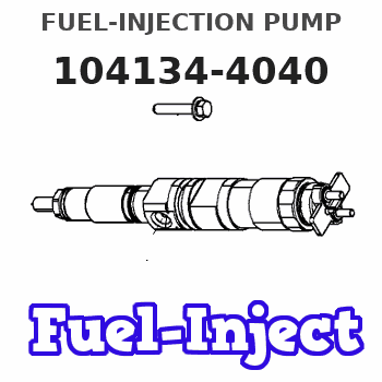
Information fuel-injection pump
BOSCH
9 410 618 093
9410618093
ZEXEL
104134-4040
1041344040
Rating:
Compare Prices: .
As an associate, we earn commssions on qualifying purchases through the links below

AXVEFHXB Compatible Fuel Injection Pump Compatible with Kubota Excavator Engine Parts 1041344040 9410618093
AXVEFHXB Compatible with Kubota excavator engines, designed to meet the specifications of model numbers 104134-4040 and 9410618093 Compatible With integration. || Engineered Compatible With enhanced fuel efficiency, this fuel injection pump optimizes engine performance in various terrain and conditions. || Built with materials to withstand the rigors of heavy-duty applications, ensuring reliable in demanding environments. || Designed Compatible With straightforward installation, facilitating quick replacement and downtime to keep your excavator operational. || Versatile usage across multiple Kubota excavator models makes this fuel injection pump a flexible solution Compatible With construction and excavation needs. || Maintains consistent fuel flow Compatible With improved engine longevity, reducing the risk of mechanical failures Compatible With dependable performance on the job. || Meets industry standards Compatible With compatibility and reliability, providing peace of mind Compatible With operators relying on their machinery in critical tasks.
AXVEFHXB Compatible with Kubota excavator engines, designed to meet the specifications of model numbers 104134-4040 and 9410618093 Compatible With integration. || Engineered Compatible With enhanced fuel efficiency, this fuel injection pump optimizes engine performance in various terrain and conditions. || Built with materials to withstand the rigors of heavy-duty applications, ensuring reliable in demanding environments. || Designed Compatible With straightforward installation, facilitating quick replacement and downtime to keep your excavator operational. || Versatile usage across multiple Kubota excavator models makes this fuel injection pump a flexible solution Compatible With construction and excavation needs. || Maintains consistent fuel flow Compatible With improved engine longevity, reducing the risk of mechanical failures Compatible With dependable performance on the job. || Meets industry standards Compatible With compatibility and reliability, providing peace of mind Compatible With operators relying on their machinery in critical tasks.

Original Fuel Injection Pump Compatible With Kubota Perkins 104134-4040 9410618093 Excavator Engine Parts
YERCBX Space optimization: Compact in size, it is convenient to install in the limited space of a vehicle || Easy to maintain: The structural design facilitates daily maintenance and upkeep || It can work normally under different conditions || Lightweight design: Utilizing lightweight materials to reduce the weight of the vehicle || Enhance the engine's power output
YERCBX Space optimization: Compact in size, it is convenient to install in the limited space of a vehicle || Easy to maintain: The structural design facilitates daily maintenance and upkeep || It can work normally under different conditions || Lightweight design: Utilizing lightweight materials to reduce the weight of the vehicle || Enhance the engine's power output

1pc Fuel Pump 104134-4040 9410618093 Compatible With Kubota Perkins Excavator Engine Accessories Parts Replacement Fuel Supply System
KDOVANPIX Adapt to different types of engines. || Low working noise and stable operation. || Compact structure, saving installation space || Control the fuel output and stabilize the common rail pressure. || Adapt to various working conditions and provide stable pressure for the engine.
KDOVANPIX Adapt to different types of engines. || Low working noise and stable operation. || Compact structure, saving installation space || Control the fuel output and stabilize the common rail pressure. || Adapt to various working conditions and provide stable pressure for the engine.
You can express buy:
USD 393.12
01-07-2025
01-07-2025
China Made New Fuel Injection Pump Head 104134-4040 Fits for Perkins
Components :
| 0. | INJECTION-PUMP ASSEMBLY | 104134-4040 |
| 1. | _ | |
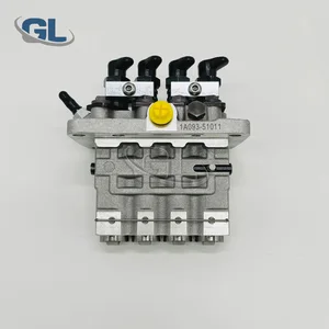
| 2. | FUEL INJECTION PUMP | |
| 3. | NUMBER PLATE | |
| 4. | _ | |
| 5. | CAPSULE | |
| 6. | ADJUSTING DEVICE | |
| 7. | NOZZLE AND HOLDER ASSY | |
| 8. | Nozzle and Holder | |
| 9. | Open Pre:MPa(Kqf/cm2) | |
| 10. | NOZZLE-HOLDER | |
| 11. | NOZZLE |
Scheme ###:
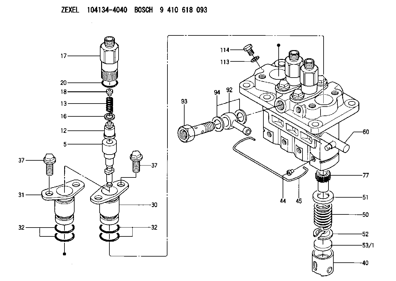
| 5. | [4] | 140163-2420 | PLUNGER-AND-BARREL ASSY |
| 12. | [4] | 140110-3720 | DELIVERY-VALVE ASSEMBLY |
| 13. | [4] | 140112-1700 | COMPRESSION SPRING |
| 16. | [4] | 140115-1400 | GASKET |
| 17. | [4] | 140116-7600 | FITTING |
| 18. | [4] | 140117-1800 | SLOTTED WASHER |
| 20. | [4] | 016500-1520 | O-RING |
| 30. | [3] | 140131-0521 | FLANGE BUSHING |
| 31. | [1] | 140131-1021 | FLANGE BUSHING |
| 32. | [8] | 016550-1920 | O-RING |
| 32. | [8] | 016550-1920 | O-RING |
| 37. | [8] | 140124-0200 | BLEEDER SCREW |
| 37. | [8] | 140124-0200 | BLEEDER SCREW |
| 40. | [4] | 140200-1620 | TAPPET |
| 44. | [4] | 140212-0300 | BEARING PIN |
| 45. | [1] | 140213-1500 | LOCKING WASHER |
| 50. | [4] | 140215-1900 | COMPRESSION SPRING |
| 51. | [4] | 140216-0800 | SLOTTED WASHER |
| 52. | [4] | 140217-2200 | SLOTTED WASHER |
| 53/1. | [1] | 140217-5000 | PLATE D19T2.60 |
| 53/1. | [1] | 140217-5100 | PLATE D19T2.65 |
| 53/1. | [1] | 140217-5200 | PLATE D19T2.70 |
| 53/1. | [1] | 140217-5300 | PLATE D19T2.75 |
| 53/1. | [1] | 140217-5400 | PLATE D19T2.80 |
| 53/1. | [1] | 140217-5500 | PLATE D19T2.85 |
| 53/1. | [1] | 140217-5600 | PLATE D19T2.90 |
| 53/1. | [1] | 140217-5700 | PLATE D19T2.95 |
| 53/1. | [1] | 140217-5800 | PLATE D19T3.00 |
| 53/1. | [1] | 140217-5900 | PLATE D19T3.05 |
| 53/1. | [1] | 140217-6000 | PLATE D19T3.10 |
| 53/1. | [1] | 140217-6100 | PLATE D19T3.15 |
| 53/1. | [1] | 140217-6200 | PLATE D19T3.20 |
| 53/1. | [1] | 140217-6300 | PLATE D19T3.25 |
| 53/1. | [1] | 140217-6400 | PLATE D19T3.30 |
| 53/1. | [1] | 140217-6500 | PLATE D19T3.35 |
| 53/1. | [1] | 140217-6600 | PLATE D19T3.40 |
| 53/1. | [1] | 140217-6700 | PLATE D19T3.45 |
| 53/1. | [1] | 140217-6800 | PLATE D19T3.50 |
| 53/1. | [1] | 140217-6900 | PLATE D19T3.55 |
| 53/1. | [1] | 140217-7000 | PLATE D19T3.60 |
| 53/1. | [1] | 140217-7100 | PLATE D19T3.65 |
| 53/1. | [1] | 140217-7200 | PLATE D19T3.70 |
| 53/1. | [1] | 140217-7300 | PLATE D19T3.75 |
| 53/1. | [1] | 140217-7400 | PLATE D19T3.80 |
| 53/1. | [1] | 140217-7500 | PLATE D19T3.85 |
| 53/1. | [1] | 140217-7600 | PLATE D19T3.90 |
| 53/1. | [1] | 140217-7700 | PLATE D19T3.95 |
| 53/1. | [1] | 140217-7800 | PLATE D19T4.00 |
| 53/1. | [1] | 140217-7900 | PLATE D19T4.05 |
| 53/1. | [1] | 140217-8000 | PLATE D19T4.10 |
| 53/1. | [1] | 140253-2000 | PLATE |
| 53/1. | [1] | 140253-2100 | PLATE |
| 53/1. | [1] | 140253-2200 | PLATE |
| 53/1. | [1] | 140253-2300 | PLATE |
| 53/1. | [1] | 140253-2400 | PLATE |
| 53/1. | [1] | 140253-2500 | PLATE |
| 53/1. | [1] | 140253-2600 | PLATE |
| 53/1. | [1] | 140253-2700 | PLATE |
| 53/1. | [1] | 140253-2800 | PLATE |
| 53/1. | [1] | 140253-2900 | PLATE |
| 53/1. | [1] | 140253-3000 | PLATE |
| 53/1. | [1] | 140253-3100 | PLATE |
| 53/1. | [1] | 140253-3200 | PLATE |
| 53/1. | [1] | 140253-3300 | PLATE |
| 53/1. | [1] | 140253-3400 | PLATE |
| 53/1. | [1] | 140253-3500 | PLATE |
| 53/1. | [1] | 140253-3600 | PLATE |
| 53/1. | [1] | 140253-3700 | PLATE |
| 53/1. | [1] | 140253-3800 | PLATE |
| 53/1. | [1] | 140253-3900 | PLATE |
| 53/1. | [1] | 140253-4000 | PLATE |
| 53/1. | [1] | 140253-4100 | PLATE |
| 53/1. | [1] | 140253-4200 | PLATE |
| 53/1. | [1] | 140253-4300 | PLATE |
| 53/1. | [1] | 140253-4400 | PLATE |
| 53/1. | [1] | 140253-4500 | PLATE |
| 53/1. | [1] | 140253-4600 | PLATE |
| 53/1. | [1] | 140253-4700 | PLATE |
| 53/1. | [1] | 140253-4800 | PLATE |
| 53/1. | [1] | 140253-4900 | PLATE |
| 60. | [1] | 140243-5620 | CONTROL RACK |
| 77. | [4] | 140241-2700 | CONTROL SLEEVE |
| 92. | [1] | 029711-2050 | INLET UNION |
| 93. | [1] | 140402-2100 | EYE BOLT |
| 94. | [2] | 026512-1540 | GASKET D15.4&12.2T1.50 |
| 113. | [2] | 026508-1240 | GASKET D11.9&8.2T1 |
| 114. | [1] | 140420-1400 | BLEEDER SCREW |
Include in #1:
106673-2590
as _
Include in #2:
104134-4040
as INJECTION-PUMP ASSEMBLY
Cross reference number
Zexel num
Bosch num
Firm num
Name
Information:
2. Remove bolts (1) that hold cover (2) in position.3. Remove cover (2). 4. Remove bolts (3), retainer (4) and automatic timing advance (5).Install Automatic Timing Advance
1. Put automatic timing advance (1) in position in the housing. 2. Install retainer (3) and bolts (2).3. Check fuel injection pump timing with tool (A). See CAMSHAFT TIMING FOR THE FUEL INJECTION PUMP in TESTING AND ADJUSTING.4. Tighten bolts (2) evenly to a torque of 20 lb.ft. (25 N m). Remove tool (A).5. Tighten bolts (2) to a torque of 100 5 lb.ft. (135 7 N m).6. Turn the crankshaft two complete turns and check the camshaft timing again. 7. Install cover (4) and the bolts.Disassemble Automatic Timing Advance
start by:a) remove automatic timing advance 1. Remove ring (1) and gear assembly (2) from the flange assembly.2. Remove the slides from the weights. 3. Remove springs (4) and weights (3) from the flange assembly.Assemble Automatic Timing Advance
1. Put weights (2) in position in flange assembly (1) as shown.2. Install springs (3) in flange assembly (1). 3. If pistons (6) were removed from the gear assembly because of wear, use new parts for replacement. Install new pistons (6) until they are .435 .005 in. (11.05 .13 mm) above the inside surface of gear assembly (4). Move the metal (peen) on the outside surface of gear assembly (4) in four places around each piston to hold them in position.4. Use 1P808 General Purpose Lubricant to hold slides (5) in position on gear assembly (4).5. Install gear assembly (4) on flange assembly (1). Make sure slides (5) fit in grooves of the weights.6. Install the ring that holds gear assembly (4) to the flange assembly.end by:a) install automatic timing advance