Information fuel-injection pump
BOSCH
9 410 618 463
9410618463
ZEXEL
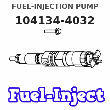
104134-4032
1041344032
ISHIKAWAJIMA-S
131017691
131017691
Rating:
Compare Prices: .
As an associate, we earn commssions on qualifying purchases through the links below

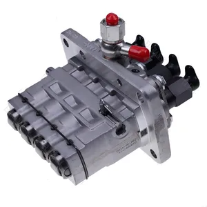
104134-4032 104134-4030 Fuel Injection Pump Compatible with New Holland 1920 TC45A TC40 TT50A TC40A TC45D TC45DA TC40D TC45 TC35 TC40DA TC35A TC35D TT45A TC35DA CASE DX35 DX40
OfkZynodor Part Name: Fuel Injection Pump || Part Number:104134-4032 104134-4030 || Application:Compatible with New Holland 1920 TC45A TC40 TT50A TC40A TC45D TC45DA TC40D TC45 TC35 TC40DA TC35A TC35D TT45A TC35DA CASE DX35 DX40 || Please make sure to carefully compare the photos and check the part numbers before making the purchase. If you are unable to confirm your engine model or part number, please leave us a message and we will assist you in confirming that the product you purchase is the one you need. || Your order is not merely a single purchase but the beginning of a cooperative journey, aiming to ensure the safe and smooth operation of your vehicle. We are proud to offer you reliable precision engineering components and unparalleled services.
OfkZynodor Part Name: Fuel Injection Pump || Part Number:104134-4032 104134-4030 || Application:Compatible with New Holland 1920 TC45A TC40 TT50A TC40A TC45D TC45DA TC40D TC45 TC35 TC40DA TC35A TC35D TT45A TC35DA CASE DX35 DX40 || Please make sure to carefully compare the photos and check the part numbers before making the purchase. If you are unable to confirm your engine model or part number, please leave us a message and we will assist you in confirming that the product you purchase is the one you need. || Your order is not merely a single purchase but the beginning of a cooperative journey, aiming to ensure the safe and smooth operation of your vehicle. We are proud to offer you reliable precision engineering components and unparalleled services.

Fuel Injection Pump SBA131017690 SBA131017691 for New Holland Tractor 1920 TC45A TC40 TC45D TC35A TT45A
FGNTWP Part Number:104134-4011, 104134-4014, 104134-4032, 1041344011, 1041344014, 1041344032, SBA131017691, SBA131017690, SBA131017691R || Application:Fit For New Holland Tractor: 1920, TC45A, TC40, TT50A, TC40A, TC45D, TC45DA, TC40D, TC45, TC35, TC40DA, TC35A, TC35D, TT45A, TC35DA
FGNTWP Part Number:104134-4011, 104134-4014, 104134-4032, 1041344011, 1041344014, 1041344032, SBA131017691, SBA131017690, SBA131017691R || Application:Fit For New Holland Tractor: 1920, TC45A, TC40, TT50A, TC40A, TC45D, TC45DA, TC40D, TC45, TC35, TC40DA, TC35A, TC35D, TT45A, TC35DA

IMIFAFTAbT 104134-4030 104134-4032 Fuel Injection Pump for New Holland 1920 TC45A TC40 TT50A TC40A TC45D TC45DA TC40D TC45 TC35 TC40DA TC35A TC35D TT45A TC35DA for Case DX40 D40 DX45 DX35 D45 D35
IMIFAFTAbT Part Name:Fuel Injection Pump 104134-4030 104134-4032 || Part Number:104134-4030 104134-4032 || APPlication: Compatible with New Holland 1920 TC45A TC40 TT50A TC40A TC45D TC45DA TC40D TC45 TC35 TC40DA TC35A TC35D TT45A TC35DA for Case DX40 D40 DX45 DX35 D45 D35 Tractor || If you are not sure if the product is suitable please leave us a message and send us your original || product picture and part number and we will send the correct part after confirmation
IMIFAFTAbT Part Name:Fuel Injection Pump 104134-4030 104134-4032 || Part Number:104134-4030 104134-4032 || APPlication: Compatible with New Holland 1920 TC45A TC40 TT50A TC40A TC45D TC45DA TC40D TC45 TC35 TC40DA TC35A TC35D TT45A TC35DA for Case DX40 D40 DX45 DX35 D45 D35 Tractor || If you are not sure if the product is suitable please leave us a message and send us your original || product picture and part number and we will send the correct part after confirmation
You can express buy:

USD 709.52
13-05-2025
13-05-2025
104134-4011 104134-4014 131017690 131017691 Fuel Injection Pump For New Holland 1920 TC45A TC40 TT50A TC40A TC45D CASE DX35 DX40
USD 652.5
19-05-2025
19-05-2025
Domestic four-cylinder new pump head 104134-4032 for Perkins D404
USD 804.57
13-05-2025
13-05-2025
104134-4011 104134-4014 131017690 131017691 Fuel Injection Pump For New Holland 1920 TC45A TC40 TT50A TC40A TC45D CASE DX35 DX40
Images:
USD 392.84

[26-Jun-2025]
Components :
| 0. | INJECTION-PUMP ASSEMBLY | 104134-4032 |
| 1. | _ | |
| 2. | FUEL INJECTION PUMP | |
| 3. | NUMBER PLATE | |
| 4. | _ | |
| 5. | CAPSULE | |
| 6. | ADJUSTING DEVICE | |
| 7. | NOZZLE AND HOLDER ASSY | 105148-1170 |
| 8. | Nozzle and Holder | |
| 9. | Open Pre:MPa(Kqf/cm2) | 14.7(150) |
| 10. | NOZZLE-HOLDER | 105078-0100 |
| 11. | NOZZLE | 105007-1170 |
Scheme ###:
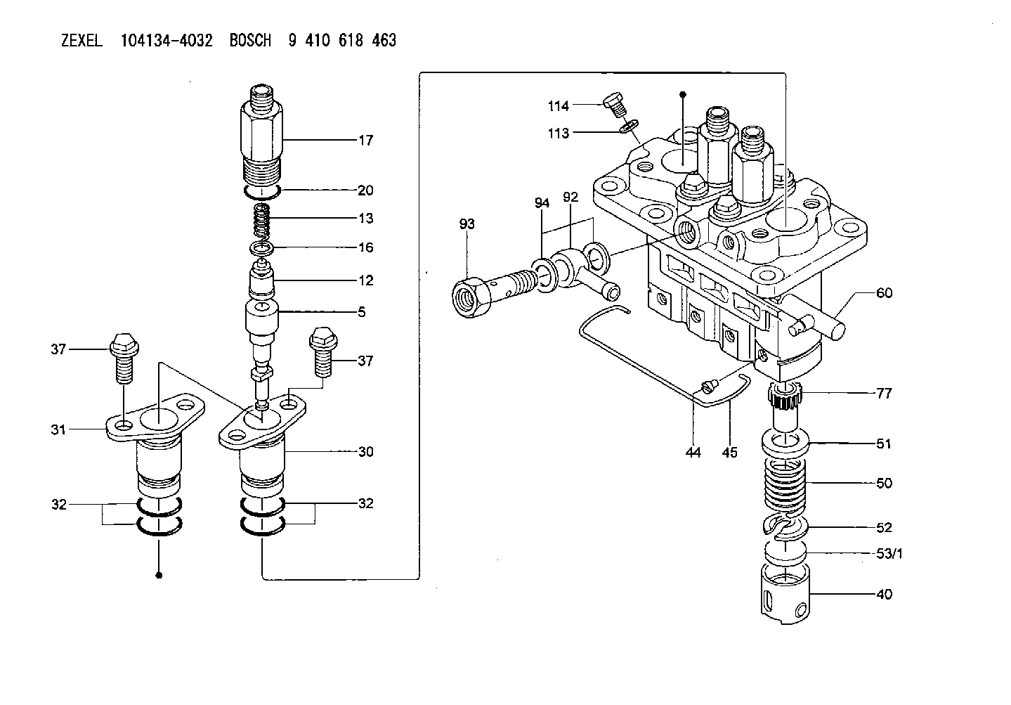
| 5. | [4] | 140163-0820 | PLUNGER-AND-BARREL ASSY |
| 12. | [4] | 140110-3620 | DELIVERY-VALVE ASSEMBLY |
| 13. | [4] | 140112-2900 | COMPRESSION SPRING |
| 16. | [4] | 140115-1400 | GASKET |
| 17. | [4] | 140116-7520 | FITTING |
| 20. | [4] | 140118-0301 | O-RING |
| 30. | [3] | 140131-0521 | FLANGE BUSHING |
| 31. | [1] | 140131-1021 | FLANGE BUSHING |
| 32. | [8] | 140118-0201 | O-RING |
| 32. | [8] | 140118-0201 | O-RING |
| 37. | [8] | 140124-0200 | BLEEDER SCREW |
| 37. | [8] | 140124-0200 | BLEEDER SCREW |
| 40. | [4] | 140200-2620 | TAPPET |
| 44. | [4] | 140212-0300 | BEARING PIN |
| 45. | [1] | 140213-1500 | LOCKING WASHER |
| 50. | [4] | 140215-1900 | COMPRESSION SPRING |
| 51. | [4] | 140216-0800 | SLOTTED WASHER |
| 52. | [4] | 140217-2200 | SLOTTED WASHER |
| 53/1. | [1] | 140217-5000 | PLATE D19T2.60 |
| 53/1. | [1] | 140217-5100 | PLATE D19T2.65 |
| 53/1. | [1] | 140217-5200 | PLATE D19T2.70 |
| 53/1. | [1] | 140217-5300 | PLATE D19T2.75 |
| 53/1. | [1] | 140217-5400 | PLATE D19T2.80 |
| 53/1. | [1] | 140217-5500 | PLATE D19T2.85 |
| 53/1. | [1] | 140217-5600 | PLATE D19T2.90 |
| 53/1. | [1] | 140217-5700 | PLATE D19T2.95 |
| 53/1. | [1] | 140217-5800 | PLATE D19T3.00 |
| 53/1. | [1] | 140217-5900 | PLATE D19T3.05 |
| 53/1. | [1] | 140217-6000 | PLATE D19T3.10 |
| 53/1. | [1] | 140217-6100 | PLATE D19T3.15 |
| 53/1. | [1] | 140217-6200 | PLATE D19T3.20 |
| 53/1. | [1] | 140217-6300 | PLATE D19T3.25 |
| 53/1. | [1] | 140217-6400 | PLATE D19T3.30 |
| 53/1. | [1] | 140217-6500 | PLATE D19T3.35 |
| 53/1. | [1] | 140217-6600 | PLATE D19T3.40 |
| 53/1. | [1] | 140217-6700 | PLATE D19T3.45 |
| 53/1. | [1] | 140217-6800 | PLATE D19T3.50 |
| 53/1. | [1] | 140217-6900 | PLATE D19T3.55 |
| 53/1. | [1] | 140217-7000 | PLATE D19T3.60 |
| 53/1. | [1] | 140217-7100 | PLATE D19T3.65 |
| 53/1. | [1] | 140217-7200 | PLATE D19T3.70 |
| 53/1. | [1] | 140217-7300 | PLATE D19T3.75 |
| 53/1. | [1] | 140217-7400 | PLATE D19T3.80 |
| 53/1. | [1] | 140217-7500 | PLATE D19T3.85 |
| 53/1. | [1] | 140217-7600 | PLATE D19T3.90 |
| 53/1. | [1] | 140217-7700 | PLATE D19T3.95 |
| 53/1. | [1] | 140217-7800 | PLATE D19T4.00 |
| 53/1. | [1] | 140217-7900 | PLATE D19T4.05 |
| 53/1. | [1] | 140217-8000 | PLATE D19T4.10 |
| 53/1. | [1] | 140253-2000 | PLATE |
| 53/1. | [1] | 140253-2100 | PLATE |
| 53/1. | [1] | 140253-2200 | PLATE |
| 53/1. | [1] | 140253-2300 | PLATE |
| 53/1. | [1] | 140253-2400 | PLATE |
| 53/1. | [1] | 140253-2500 | PLATE |
| 53/1. | [1] | 140253-2600 | PLATE |
| 53/1. | [1] | 140253-2700 | PLATE |
| 53/1. | [1] | 140253-2800 | PLATE |
| 53/1. | [1] | 140253-2900 | PLATE |
| 53/1. | [1] | 140253-3000 | PLATE |
| 53/1. | [1] | 140253-3100 | PLATE |
| 53/1. | [1] | 140253-3200 | PLATE |
| 53/1. | [1] | 140253-3300 | PLATE |
| 53/1. | [1] | 140253-3400 | PLATE |
| 53/1. | [1] | 140253-3500 | PLATE |
| 53/1. | [1] | 140253-3600 | PLATE |
| 53/1. | [1] | 140253-3700 | PLATE |
| 53/1. | [1] | 140253-3800 | PLATE |
| 53/1. | [1] | 140253-3900 | PLATE |
| 53/1. | [1] | 140253-4000 | PLATE |
| 53/1. | [1] | 140253-4100 | PLATE |
| 53/1. | [1] | 140253-4200 | PLATE |
| 53/1. | [1] | 140253-4300 | PLATE |
| 53/1. | [1] | 140253-4400 | PLATE |
| 53/1. | [1] | 140253-4500 | PLATE |
| 53/1. | [1] | 140253-4600 | PLATE |
| 53/1. | [1] | 140253-4700 | PLATE |
| 53/1. | [1] | 140253-4800 | PLATE |
| 53/1. | [1] | 140253-4900 | PLATE |
| 60. | [1] | 140243-5620 | CONTROL RACK |
| 77. | [4] | 140241-2700 | CONTROL SLEEVE |
| 92. | [1] | 029711-2050 | INLET UNION |
| 93. | [1] | 140402-1300 | EYE BOLT |
| 94. | [2] | 026512-1540 | GASKET D15.4&12.2T1.50 |
| 113. | [1] | 026508-1240 | GASKET D11.9&8.2T1 |
| 114. | [1] | 140420-1400 | BLEEDER SCREW |
Include in #1:
106673-2490
as _
Include in #2:
104134-4032
as INJECTION-PUMP ASSEMBLY
Cross reference number
Zexel num
Bosch num
Firm num
Name
Information:
start by:a) remove vibration damper and pulley
The crankshaft front seal and wear sleeve come as a set and must be installed as a set. If a replacement of the seal is to be made, a replacement of the wear sleeve must also be made.
1. Make at least three holes in seal (1) with a hammer and a sharp punch. 2. Use tool (A) to remove seal (1). 3. Install tool (C) into the seal bore.4. Install tool (B) between tool (C) and the wear sleeve. Turn tool (B) until the edge of the tool makes a flat place (crease) in the wear sleeve. Do this in two or more places until the wear sleeve is loose.5. Remove tool (C) and the wear sleeve by hand.Install Crankshaft Front Seal And Wear Sleeve
The crankshaft seal and wear sleeve come as a set and must not be separated from each other at any time. Carefully read Special Instruction, Form No. SMHS8508, that is included with each seal and wear sleeve before any handling of the seal group is made.
1. Install the front crankshaft seal and wear sleeve with tooling (A). Use the procedures which follow: a. Clean and make a preparation of the wear sleeve inside diameter and crankshaft outside diameter with 6V1541 Quick Cure Primer. Make an application of 9S3265 Retaining Compound to the crankshaft outside diameter before the wear sleeve is installed on the crankshaft. Do not let any Quick Cure Primer or Retaining Compound get on the lip of the seal.
TYPICAL EXAMPLEb. Install locator (3) and bolts (4) on the crankshaft.c. Seal (1) and wear sleeve (2) must be installed dry.
Make sure the seal is installed with the part number and the arrows showing crankshaft rotation toward the outside.
The front and rear seals and wear sleeves have different spiral grooves in the seal. Because of this type of design, the front seal group for an engine is different from the rear seal group. If a seal group is installed on the wrong end of the engine, oil can actually be taken out of the engine instead of moving the oil back into the engine.
d. Put wear sleeve (2) and seal (1) as a unit in position on locator (3).e. Put installer (5) in position on locator (3).f. Put clean engine oil on the face of nut (6) and its contact area on installer (5). Install nut (6) on locator (3).g. Tighten nut (6) until the inside surface of installer (5) comes in contact with locator (3).h. Remove tooling (A) from the crankshaft seal and wear sleeve. Tooling (A) will install the seal and wear sleeve to the correct depth on the crankshaft.end by:a) install vibration damper and pulley