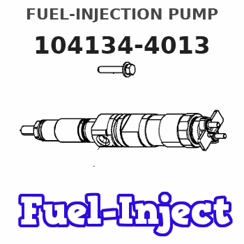
Information fuel-injection pump
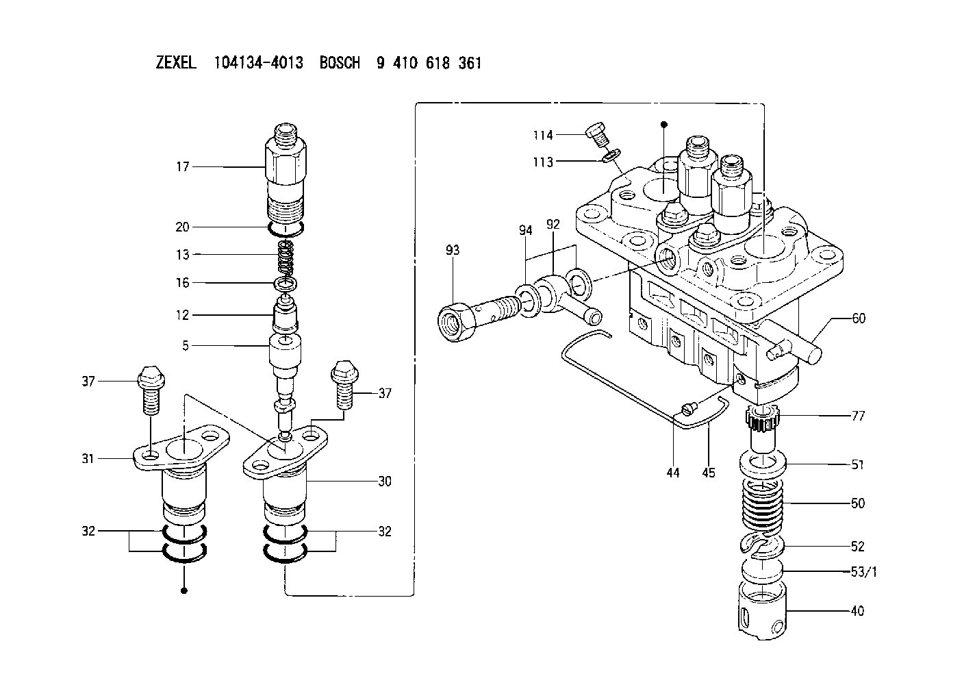
BOSCH
9 410 618 361
9410618361
ZEXEL
104134-4013
1041344013
ISHIKAWAJIMA-S
131017601
131017601
Rating:
Compare Prices: .
As an associate, we earn commssions on qualifying purchases through the links below

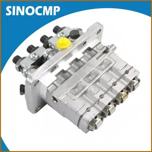
Fuel Injection Pump 104134-4013 131017601 584A331412 Suitable for Perkins Serie 100 104.19 Serie 400 404 Suitable for Cummins QSM11 Engine
CCXXMMYY Product Name:Fuel Injection Pump || Product Number:104134-4013 131017601 584A331412 || Application: Suitable for Perkins Serie 100 104.19 Serie 400 404 Suitable for Cummins QSM11 Engine || TIP: This product requires coding programs, and we need you to provide us with the machine serial number or engine nameplate. thank you || Strict Quality Control: Every Product Is Subjected To Multiple Quality Tests, We Ensure That Products Are Delivered To Customers With High Quality
CCXXMMYY Product Name:Fuel Injection Pump || Product Number:104134-4013 131017601 584A331412 || Application: Suitable for Perkins Serie 100 104.19 Serie 400 404 Suitable for Cummins QSM11 Engine || TIP: This product requires coding programs, and we need you to provide us with the machine serial number or engine nameplate. thank you || Strict Quality Control: Every Product Is Subjected To Multiple Quality Tests, We Ensure That Products Are Delivered To Customers With High Quality

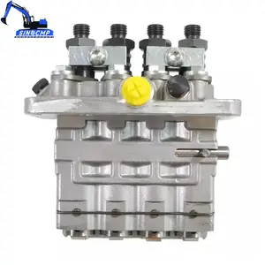
IMELBUFF 131017601 104134-4013 9410618361 Fuel Injection Pump for Perkins 100 104.19 400 404 Series Engine Cummins QSM11 Engine
IMELBUFF 🚜Part Number: 104134-4013 131017601 9410618361 || 🚜Engine Model: for Cummins Marine QSM11 Engine || 🚜Application: for Perkins 100 104.19 400 404 Series Engine || 🚜Warm Tips: If you are not sure that the pump is suitable for your vehicle, please send us email with your vehicle engine model and fuel pump part number || 🚜Service: 6-months-warranty and 24 hour support for customer service. Please feel free to contact us by email if you have any question with the product
IMELBUFF 🚜Part Number: 104134-4013 131017601 9410618361 || 🚜Engine Model: for Cummins Marine QSM11 Engine || 🚜Application: for Perkins 100 104.19 400 404 Series Engine || 🚜Warm Tips: If you are not sure that the pump is suitable for your vehicle, please send us email with your vehicle engine model and fuel pump part number || 🚜Service: 6-months-warranty and 24 hour support for customer service. Please feel free to contact us by email if you have any question with the product
You can express buy:
USD 864.58
13-05-2025
13-05-2025
Fuel Injection Pump 131017601, 104134-4013 For Cummins QSM11 Marine For Perkins Series 100 104.19 Series 400 404, Original
USD 1157.7
05-05-2025
05-05-2025
Fuel Injection Pump 104134-4013 131017601 For Perkins Series 100 104.19 400 404 For Cummins QSM11 Marine
Images:
USD 1157.7

[05-May-2025]
USD 393.12

[01-Jul-2025]
Components :
| 0. | INJECTION-PUMP ASSEMBLY | 104134-4013 |
| 1. | _ | |
| 2. | FUEL INJECTION PUMP | |
| 3. | NUMBER PLATE | |
| 4. | _ | |
| 5. | CAPSULE | |
| 6. | ADJUSTING DEVICE | |
| 7. | NOZZLE AND HOLDER ASSY | 105148-1170 |
| 8. | Nozzle and Holder | |
| 9. | Open Pre:MPa(Kqf/cm2) | 14.7(150) |
| 10. | NOZZLE-HOLDER | 105078-0100 |
| 11. | NOZZLE | 105007-1170 |
Scheme ###:
| 5. | [4] | 140163-3720 | PLUNGER-AND-BARREL ASSY |
| 12. | [4] | 140110-3620 | DELIVERY-VALVE ASSEMBLY |
| 13. | [4] | 140112-2900 | COMPRESSION SPRING |
| 16. | [4] | 140115-1400 | GASKET |
| 17. | [4] | 140116-7520 | FITTING |
| 20. | [4] | 016500-1520 | O-RING |
| 30. | [3] | 140131-0521 | FLANGE BUSHING |
| 31. | [1] | 140131-1021 | FLANGE BUSHING |
| 32. | [8] | 016550-1920 | O-RING |
| 32. | [8] | 016550-1920 | O-RING |
| 37. | [8] | 140124-0200 | BLEEDER SCREW |
| 37. | [8] | 140124-0200 | BLEEDER SCREW |
| 40. | [4] | 140200-1620 | TAPPET |
| 44. | [4] | 140212-0300 | BEARING PIN |
| 45. | [1] | 140213-1500 | LOCKING WASHER |
| 50. | [4] | 140215-1900 | COMPRESSION SPRING |
| 51. | [4] | 140216-0800 | SLOTTED WASHER |
| 52. | [4] | 140217-2200 | SLOTTED WASHER |
| 53/1. | [1] | 140217-5000 | PLATE D19T2.60 |
| 53/1. | [1] | 140217-5100 | PLATE D19T2.65 |
| 53/1. | [1] | 140217-5200 | PLATE D19T2.70 |
| 53/1. | [1] | 140217-5300 | PLATE D19T2.75 |
| 53/1. | [1] | 140217-5400 | PLATE D19T2.80 |
| 53/1. | [1] | 140217-5500 | PLATE D19T2.85 |
| 53/1. | [1] | 140217-5600 | PLATE D19T2.90 |
| 53/1. | [1] | 140217-5700 | PLATE D19T2.95 |
| 53/1. | [1] | 140217-5800 | PLATE D19T3.00 |
| 53/1. | [1] | 140217-5900 | PLATE D19T3.05 |
| 53/1. | [1] | 140217-6000 | PLATE D19T3.10 |
| 53/1. | [1] | 140217-6100 | PLATE D19T3.15 |
| 53/1. | [1] | 140217-6200 | PLATE D19T3.20 |
| 53/1. | [1] | 140217-6300 | PLATE D19T3.25 |
| 53/1. | [1] | 140217-6400 | PLATE D19T3.30 |
| 53/1. | [1] | 140217-6500 | PLATE D19T3.35 |
| 53/1. | [1] | 140217-6600 | PLATE D19T3.40 |
| 53/1. | [1] | 140217-6700 | PLATE D19T3.45 |
| 53/1. | [1] | 140217-6800 | PLATE D19T3.50 |
| 53/1. | [1] | 140217-6900 | PLATE D19T3.55 |
| 53/1. | [1] | 140217-7000 | PLATE D19T3.60 |
| 53/1. | [1] | 140217-7100 | PLATE D19T3.65 |
| 53/1. | [1] | 140217-7200 | PLATE D19T3.70 |
| 53/1. | [1] | 140217-7300 | PLATE D19T3.75 |
| 53/1. | [1] | 140217-7400 | PLATE D19T3.80 |
| 53/1. | [1] | 140217-7500 | PLATE D19T3.85 |
| 53/1. | [1] | 140217-7600 | PLATE D19T3.90 |
| 53/1. | [1] | 140217-7700 | PLATE D19T3.95 |
| 53/1. | [1] | 140217-7800 | PLATE D19T4.00 |
| 53/1. | [1] | 140217-7900 | PLATE D19T4.05 |
| 53/1. | [1] | 140217-8000 | PLATE D19T4.10 |
| 53/1. | [1] | 140253-2000 | PLATE |
| 53/1. | [1] | 140253-2100 | PLATE |
| 53/1. | [1] | 140253-2200 | PLATE |
| 53/1. | [1] | 140253-2300 | PLATE |
| 53/1. | [1] | 140253-2400 | PLATE |
| 53/1. | [1] | 140253-2500 | PLATE |
| 53/1. | [1] | 140253-2600 | PLATE |
| 53/1. | [1] | 140253-2700 | PLATE |
| 53/1. | [1] | 140253-2800 | PLATE |
| 53/1. | [1] | 140253-2900 | PLATE |
| 53/1. | [1] | 140253-3000 | PLATE |
| 53/1. | [1] | 140253-3100 | PLATE |
| 53/1. | [1] | 140253-3200 | PLATE |
| 53/1. | [1] | 140253-3300 | PLATE |
| 53/1. | [1] | 140253-3400 | PLATE |
| 53/1. | [1] | 140253-3500 | PLATE |
| 53/1. | [1] | 140253-3600 | PLATE |
| 53/1. | [1] | 140253-3700 | PLATE |
| 53/1. | [1] | 140253-3800 | PLATE |
| 53/1. | [1] | 140253-3900 | PLATE |
| 53/1. | [1] | 140253-4000 | PLATE |
| 53/1. | [1] | 140253-4100 | PLATE |
| 53/1. | [1] | 140253-4200 | PLATE |
| 53/1. | [1] | 140253-4300 | PLATE |
| 53/1. | [1] | 140253-4400 | PLATE |
| 53/1. | [1] | 140253-4500 | PLATE |
| 53/1. | [1] | 140253-4600 | PLATE |
| 53/1. | [1] | 140253-4700 | PLATE |
| 53/1. | [1] | 140253-4800 | PLATE |
| 53/1. | [1] | 140253-4900 | PLATE |
| 60. | [1] | 140243-5620 | CONTROL RACK |
| 77. | [4] | 140241-4200 | CONTROL SLEEVE |
| 92. | [1] | 029711-2050 | INLET UNION |
| 93. | [1] | 140402-1300 | EYE BOLT |
| 94. | [2] | 026512-1540 | GASKET D15.4&12.2T1.50 |
| 113. | [1] | 026508-1240 | GASKET D11.9&8.2T1 |
| 114. | [1] | 140420-1400 | BLEEDER SCREW |
Include in #1:
101602-1320
as _
Include in #2:
104134-4013
as INJECTION-PUMP ASSEMBLY
Cross reference number
Zexel num
Bosch num
Firm num
Name
131017601 ISHIKAWAJIMA-S
FUEL-INJECTION PUMP
* K 23AD FUEL INJECTION PUMP PFR-4KX PFR
* K 23AD FUEL INJECTION PUMP PFR-4KX PFR
Information:
1. Disconnect two fuel lines (1) from the transfer pump.2. Disconnect three lines (2) from the fuel injection pump housing and air-fuel ratio control. 3. Remove bolt (3) from the governor linkage.4. Remove three bolts (5) from the brackets that hold the fuel injection pump housing to the cylinder block.5. Remove four bolts (4). 6. Fasten a hoist to fuel injection pump housing and governor (6). Slide the fuel injection pump housing to the rear and remove it. The weight of the fuel injection pump housing is 110 lb. (49.5 kg). 7. Remove two O-ring seals (8) and O-ring seal (7).Install Fuel Injection Pump Housing And Governor
Make sure the outer surface of the fuel system and the surfaces that come in contact with it are clean.
1. Inspect the O-ring seals for wear or damage. Make a replacement if necessary. 2. Install O-ring seals (1) and (2) on the fuel injection pump housing. 3. Fasten a hoist to fuel injection pump housing and governor (3) and lower it into position. Install the four bolts that hold the fuel system to the cylinder block. 4. Install three bolts (5).5. Connect governor linkage (4) to the governor. 6. Connect line (6) to the air-fuel ratio control.7. Connect two lines (7) to the transfer pump.8. Connect two lines (8) to the fuel injection pump housing.end by:a) install fuel injection linesb) install automatic timing advance