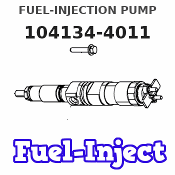
Information fuel-injection pump
BOSCH
9 410 617 204
9410617204
ZEXEL
104134-4011
1041344011
ISHIKAWAJIMA-S
131017600
131017600
Rating:
Compare Prices: .
As an associate, we earn commssions on qualifying purchases through the links below

IMELBUFF 131017600 104134-4011 9410617204 Fuel Injection Pump for Perkins 104.19 104-19 404D-22 404C-22 404A-22 404D-22T 404D-22TA Engine
IMELBUFF 🚜Part Number: 131017600 104134-4011 9410617204 || 🚜Engine Model: for Perkins Engine 104.19, 104-19, 404D-22, 404C-22, 404A-22, 404D-22T, 404D-22TA, 403F-15T, 404F-22, 404F-22T || 🚜Fuel Pump: 131017602 replaces 131017600 since 24/07/2007, 131017602 replaces 131017601 since 03/11/2006, and 131010080 replaces 131017602 since 22/02/2008 || 🚜Warm Tips: If you are not sure that the pump is suitable for your vehicle, please send us email with your vehicle engine model and fuel pump part number || 🚜Service: 6-months-warranty and 24 hour support for customer service. Please feel free to contact us by amazon email if you have any question with the product. Thank you for choosing IMELBUFF
IMELBUFF 🚜Part Number: 131017600 104134-4011 9410617204 || 🚜Engine Model: for Perkins Engine 104.19, 104-19, 404D-22, 404C-22, 404A-22, 404D-22T, 404D-22TA, 403F-15T, 404F-22, 404F-22T || 🚜Fuel Pump: 131017602 replaces 131017600 since 24/07/2007, 131017602 replaces 131017601 since 03/11/2006, and 131010080 replaces 131017602 since 22/02/2008 || 🚜Warm Tips: If you are not sure that the pump is suitable for your vehicle, please send us email with your vehicle engine model and fuel pump part number || 🚜Service: 6-months-warranty and 24 hour support for customer service. Please feel free to contact us by amazon email if you have any question with the product. Thank you for choosing IMELBUFF

Fuel Injection Pump Compatible For Kubota Perkins Engine 404D-22 404C-22 104-19 131017600 104134-4011 9410617204 Excavator Engine Parts
SDETASOQ Precise control: precise fuel injection, optimized combustion efficiency, reduced fuel consumption, and improved engine power output || Long lifespan and low maintenance: using high-strength wear-resistant alloy materials and corrosion-resistant coatings to reduce maintenance costs and downtime || Stable operation under all operating conditions: tested in extreme environments, continuously stable, and adaptable to various complex road and climate conditions || Silent and efficient operation: Adopting a noise reduction structure, it can maintain quietness even during high-speed operation, without interfering with the driving experience || Fuel Injection Pump Compatible For Kubota Perkins Engine 404D-22 404C-22 104-19 131017600 104134-4011 9410617204 Excavator Engine Parts
SDETASOQ Precise control: precise fuel injection, optimized combustion efficiency, reduced fuel consumption, and improved engine power output || Long lifespan and low maintenance: using high-strength wear-resistant alloy materials and corrosion-resistant coatings to reduce maintenance costs and downtime || Stable operation under all operating conditions: tested in extreme environments, continuously stable, and adaptable to various complex road and climate conditions || Silent and efficient operation: Adopting a noise reduction structure, it can maintain quietness even during high-speed operation, without interfering with the driving experience || Fuel Injection Pump Compatible For Kubota Perkins Engine 404D-22 404C-22 104-19 131017600 104134-4011 9410617204 Excavator Engine Parts
You can express buy:

USD 709.52
13-05-2025
13-05-2025
104134-4011 104134-4014 131017690 131017691 Fuel Injection Pump For New Holland 1920 TC45A TC40 TT50A TC40A TC45D CASE DX35 DX40
USD 804.57
13-05-2025
13-05-2025
104134-4011 104134-4014 131017690 131017691 Fuel Injection Pump For New Holland 1920 TC45A TC40 TT50A TC40A TC45D CASE DX35 DX40
USD 387.8
07-05-2025
07-05-2025
China Made New Fuel Injection Pump Head 131017600 104134-4011 Fits for Perkins
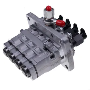
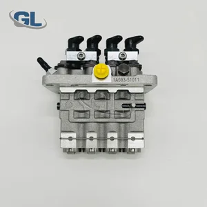
Images:
USD 387.8

[07-May-2025]
USD 350.27

[01-May-2025]
Components :
| 0. | INJECTION-PUMP ASSEMBLY | 104134-4011 |
| 1. | _ | |
| 2. | FUEL INJECTION PUMP | |
| 3. | NUMBER PLATE | |
| 4. | _ | |
| 5. | CAPSULE | |
| 6. | ADJUSTING DEVICE | |
| 7. | NOZZLE AND HOLDER ASSY | 105148-1170 |
| 8. | Nozzle and Holder | |
| 9. | Open Pre:MPa(Kqf/cm2) | 14.7{150} |
| 10. | NOZZLE-HOLDER | 105078-0100 |
| 11. | NOZZLE | 105007-1170 |
Scheme ###:
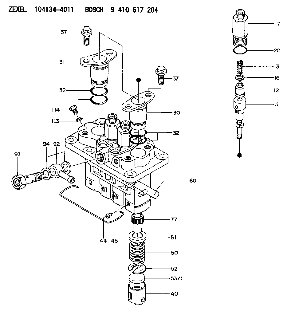
| 5. | [4] | 140154-7920 | PLUNGER-AND-BARREL ASSY |
| 12. | [4] | 140110-3620 | DELIVERY-VALVE ASSEMBLY |
| 13. | [4] | 140112-2900 | COMPRESSION SPRING |
| 16. | [4] | 140115-1400 | GASKET |
| 17. | [4] | 140116-7520 | FITTING |
| 20. | [4] | 016500-1520 | O-RING |
| 30. | [3] | 140131-0521 | FLANGE BUSHING |
| 31. | [1] | 140131-1021 | FLANGE BUSHING |
| 32. | [8] | 016550-1920 | O-RING |
| 32. | [8] | 016550-1920 | O-RING |
| 37. | [8] | 140124-0200 | BLEEDER SCREW |
| 37. | [8] | 140124-0200 | BLEEDER SCREW |
| 40. | [4] | 140200-1620 | TAPPET |
| 44. | [4] | 140212-0300 | BEARING PIN |
| 45. | [1] | 140213-1500 | LOCKING WASHER |
| 50. | [4] | 140215-1900 | COMPRESSION SPRING |
| 51. | [4] | 140216-0800 | SLOTTED WASHER |
| 52. | [4] | 140217-2200 | SLOTTED WASHER |
| 53/1. | [1] | 140217-5000 | PLATE D19T2.60 |
| 53/1. | [1] | 140217-5100 | PLATE D19T2.65 |
| 53/1. | [1] | 140217-5200 | PLATE D19T2.70 |
| 53/1. | [1] | 140217-5300 | PLATE D19T2.75 |
| 53/1. | [1] | 140217-5400 | PLATE D19T2.80 |
| 53/1. | [1] | 140217-5500 | PLATE D19T2.85 |
| 53/1. | [1] | 140217-5600 | PLATE D19T2.90 |
| 53/1. | [1] | 140217-5700 | PLATE D19T2.95 |
| 53/1. | [1] | 140217-5800 | PLATE D19T3.00 |
| 53/1. | [1] | 140217-5900 | PLATE D19T3.05 |
| 53/1. | [1] | 140217-6000 | PLATE D19T3.10 |
| 53/1. | [1] | 140217-6100 | PLATE D19T3.15 |
| 53/1. | [1] | 140217-6200 | PLATE D19T3.20 |
| 53/1. | [1] | 140217-6300 | PLATE D19T3.25 |
| 53/1. | [1] | 140217-6400 | PLATE D19T3.30 |
| 53/1. | [1] | 140217-6500 | PLATE D19T3.35 |
| 53/1. | [1] | 140217-6600 | PLATE D19T3.40 |
| 53/1. | [1] | 140217-6700 | PLATE D19T3.45 |
| 53/1. | [1] | 140217-6800 | PLATE D19T3.50 |
| 53/1. | [1] | 140217-6900 | PLATE D19T3.55 |
| 53/1. | [1] | 140217-7000 | PLATE D19T3.60 |
| 53/1. | [1] | 140217-7100 | PLATE D19T3.65 |
| 53/1. | [1] | 140217-7200 | PLATE D19T3.70 |
| 53/1. | [1] | 140217-7300 | PLATE D19T3.75 |
| 53/1. | [1] | 140217-7400 | PLATE D19T3.80 |
| 53/1. | [1] | 140217-7500 | PLATE D19T3.85 |
| 53/1. | [1] | 140217-7600 | PLATE D19T3.90 |
| 53/1. | [1] | 140217-7700 | PLATE D19T3.95 |
| 53/1. | [1] | 140217-7800 | PLATE D19T4.00 |
| 53/1. | [1] | 140217-7900 | PLATE D19T4.05 |
| 53/1. | [1] | 140217-8000 | PLATE D19T4.10 |
| 53/1. | [1] | 140253-2000 | PLATE |
| 53/1. | [1] | 140253-2100 | PLATE |
| 53/1. | [1] | 140253-2200 | PLATE |
| 53/1. | [1] | 140253-2300 | PLATE |
| 53/1. | [1] | 140253-2400 | PLATE |
| 53/1. | [1] | 140253-2500 | PLATE |
| 53/1. | [1] | 140253-2600 | PLATE |
| 53/1. | [1] | 140253-2700 | PLATE |
| 53/1. | [1] | 140253-2800 | PLATE |
| 53/1. | [1] | 140253-2900 | PLATE |
| 53/1. | [1] | 140253-3000 | PLATE |
| 53/1. | [1] | 140253-3100 | PLATE |
| 53/1. | [1] | 140253-3200 | PLATE |
| 53/1. | [1] | 140253-3300 | PLATE |
| 53/1. | [1] | 140253-3400 | PLATE |
| 53/1. | [1] | 140253-3500 | PLATE |
| 53/1. | [1] | 140253-3600 | PLATE |
| 53/1. | [1] | 140253-3700 | PLATE |
| 53/1. | [1] | 140253-3800 | PLATE |
| 53/1. | [1] | 140253-3900 | PLATE |
| 53/1. | [1] | 140253-4000 | PLATE |
| 53/1. | [1] | 140253-4100 | PLATE |
| 53/1. | [1] | 140253-4200 | PLATE |
| 53/1. | [1] | 140253-4300 | PLATE |
| 53/1. | [1] | 140253-4400 | PLATE |
| 53/1. | [1] | 140253-4500 | PLATE |
| 53/1. | [1] | 140253-4600 | PLATE |
| 53/1. | [1] | 140253-4700 | PLATE |
| 53/1. | [1] | 140253-4800 | PLATE |
| 53/1. | [1] | 140253-4900 | PLATE |
| 60. | [1] | 140243-5620 | CONTROL RACK |
| 77. | [4] | 140241-2700 | CONTROL SLEEVE |
| 92. | [1] | 029711-2050 | INLET UNION |
| 93. | [1] | 140402-1300 | EYE BOLT |
| 94. | [2] | 026512-1540 | GASKET D15.4&12.2T1.50 |
| 113. | [1] | 026508-1240 | GASKET D11.9&8.2T1 |
| 114. | [1] | 140420-1400 | BLEEDER SCREW |
Include in #1:
101607-1130
as _
Include in #2:
104134-4011
as INJECTION-PUMP ASSEMBLY
Cross reference number
Zexel num
Bosch num
Firm num
Name
9 410 617 204
131017600 ISHIKAWAJIMA-S
FUEL-INJECTION PUMP
* K 23AD PFR-4KX PFR
* K 23AD PFR-4KX PFR
Information:
start by:a) remove governor 1. Bend the lock down. Remove two bolts (4) and torque spring (2).2. Remove high idle screw (3).3. Remove the two bolts and bracket (1). The bolt that holds the governor housing to the governor plate can be removed at this time. 4. Bend lock (7) down and remove the bolt from control lever (8). Remove shaft (5) and the control lever. Remove the lip type seals from housing (6). 5. Remove two bearings (9) from the housing. 6. Remove seat (10), spring washer (11), flat washer (12), spring washer (13) and spring (14). 7. Remove washer (16). Remove ring (17) from the seat. Remove the dowel from the seat and remove the governor bolt (15) and seat as a unit. 8. Remove the governor bolt, top washer (18), spring (19) and bottom washer (20) from the top of the servo piston.9. Remove the race, bearing and race from the bottom of the sleeve.10. Remove the lock from the flywheel assembly. Remove the flywheel assembly. 11. Bend locks (22) back. Remove bolts (25). Remove bracket (24) and pin (23) as a unit. 12. Remove shaft (26) from the bracket assembly with a hammer and punch.13. Remove levers (28) and spring (27) from the bracket assembly.14. Remove servo piston assembly (21) through the bottom of the governor plate. 15. Remove sleeve (31) from servo piston cylinder (29). Remove piston (32) from the cylinder. Remove the O-ring seals from cylinder (29) and seal (30) from the piston. 16. Remove dowel (36). Remove drive assembly (33) and stop (35). Remove the snap ring with tool (A) from the bottom of gear (34). Remove gear (34).17. Remove the bearing for gear (34) from the governor plate.Assemble Governor (Earlier)
1. If replacement of the dowels in the governor plate is necessary, see illustration for correct installation dimensions. 2. Install the bearing for drive gear (2) in the governor plate with tooling (A) until it is .020 in. (0.51 mm) from the top surface of the governor plate.3. Install drive gear (2). Install ring (1) with tool (B). 4. Put valve (4) in piston (5). Install piston (5) in sleeve (3).5. Install the O-ring seals on cylinder (6).6. Install the servo piston assembly valve (4), piston (5), sleeve (3) and cylinder (6) through the bottom of the governor plate. The valve, piston, sleeve and cylinder are parts of the servo piston assembly. Put the notch in cylinder (6) in alignment with the holes in lever (9). Install shaft (7). 8. Install pin (11) in bracket assembly (10) with the grooves in pin (11) engaged with lever (9). 9. Put the bracket assembly into position on the governor plate with pin (11) engaged with the servo piston assembly as shown. Install the bolts and locks that hold bracket assembly (10) to the governor plate. 10. Install the flyweight and gear assembly on the servo piston assembly. Install lock (22).11. Install race (17), bearing (20) and race (24) on sleeve (21). Install the
1. If replacement of the dowels in the governor plate is necessary, see illustration for correct installation dimensions. 2. Install the bearing for drive gear (2) in the governor plate with tooling (A) until it is .020 in. (0.51 mm) from the top surface of the governor plate.3. Install drive gear (2). Install ring (1) with tool (B). 4. Put valve (4) in piston (5). Install piston (5) in sleeve (3).5. Install the O-ring seals on cylinder (6).6. Install the servo piston assembly valve (4), piston (5), sleeve (3) and cylinder (6) through the bottom of the governor plate. The valve, piston, sleeve and cylinder are parts of the servo piston assembly. Put the notch in cylinder (6) in alignment with the holes in lever (9). Install shaft (7). 8. Install pin (11) in bracket assembly (10) with the grooves in pin (11) engaged with lever (9). 9. Put the bracket assembly into position on the governor plate with pin (11) engaged with the servo piston assembly as shown. Install the bolts and locks that hold bracket assembly (10) to the governor plate. 10. Install the flyweight and gear assembly on the servo piston assembly. Install lock (22).11. Install race (17), bearing (20) and race (24) on sleeve (21). Install the