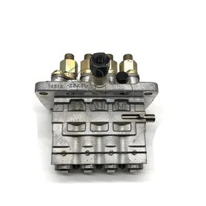
Information fuel-injection pump
BOSCH
9 410 618 077
9410618077
ZEXEL
104134-4002
1041344002
ISHIKAWAJIMA-S
131017541
131017541

Rating:
Compare Prices: .
As an associate, we earn commssions on qualifying purchases through the links below

Fuel Injection Pump 131017541 9410618077 104134-4002 for Kubota Perkins Engine
FGNTWP Part Number:131017540, 131017541, 131017542, 104134-4002, 1041344002, 9 410 618 077, 9410618077, 104134-4003, 1041344003, F 01G 09Y 002, F01G09Y002, 104134-4001, 1041344001, 9 410 617 047, 9410617047 || Applications:for Kubota Perkins Engine
FGNTWP Part Number:131017540, 131017541, 131017542, 104134-4002, 1041344002, 9 410 618 077, 9410618077, 104134-4003, 1041344003, F 01G 09Y 002, F01G09Y002, 104134-4001, 1041344001, 9 410 617 047, 9410617047 || Applications:for Kubota Perkins Engine

Fuel Injection Pump for Perkins Engine 9410618077 104134-4002 131017541
KoovDem Part Number:104642-3050 104742-3050 315-4677 336-9190 3154677 3369190 32A6527810 32A6537310 VE4/12F1250RNP2654 || Vehicle Application:For Caterpillar Skid Steer Loader 236B 242B 246C 252B 257B 259B 262C 277C 279C 287C 289C || Please verify the information provided to ensure you receive the appropriate fuel pump for your equipment. Double-checking is crucial to prevent any mistakes or hold-ups in processing your order. Should you have any inquiries or issues, feel free to reach out to us for assistance. Your attention to detail and cooperation are greatly appreciated. Thank you. || We offer a 5-month warranty and around-the-clock customer support for all our products. Feel free to contact us via email with any queries or issues you may have. Our team is committed to helping you in every possible way.
KoovDem Part Number:104642-3050 104742-3050 315-4677 336-9190 3154677 3369190 32A6527810 32A6537310 VE4/12F1250RNP2654 || Vehicle Application:For Caterpillar Skid Steer Loader 236B 242B 246C 252B 257B 259B 262C 277C 279C 287C 289C || Please verify the information provided to ensure you receive the appropriate fuel pump for your equipment. Double-checking is crucial to prevent any mistakes or hold-ups in processing your order. Should you have any inquiries or issues, feel free to reach out to us for assistance. Your attention to detail and cooperation are greatly appreciated. Thank you. || We offer a 5-month warranty and around-the-clock customer support for all our products. Feel free to contact us via email with any queries or issues you may have. Our team is committed to helping you in every possible way.
You can express buy:
USD 652.22
27-06-2025
27-06-2025
China made new High Pressure Fuel Injection Pump 131017541 104134-4002 9410618077 for perkins Engine
Images:
USD 393.12

[01-Jul-2025]
Components :
| 0. | INJECTION-PUMP ASSEMBLY | 104134-4002 |
| 1. | _ | |
| 2. | FUEL INJECTION PUMP | |
| 3. | NUMBER PLATE | |
| 4. | _ | |
| 5. | CAPSULE | |
| 6. | ADJUSTING DEVICE | |
| 7. | NOZZLE AND HOLDER ASSY | 105141-2200 |
| 8. | Nozzle and Holder | |
| 9. | Open Pre:MPa(Kqf/cm2) | 11.8{120} |
| 10. | NOZZLE-HOLDER | 105071-0640 |
| 11. | NOZZLE | 105000-1010 |
Scheme ###:
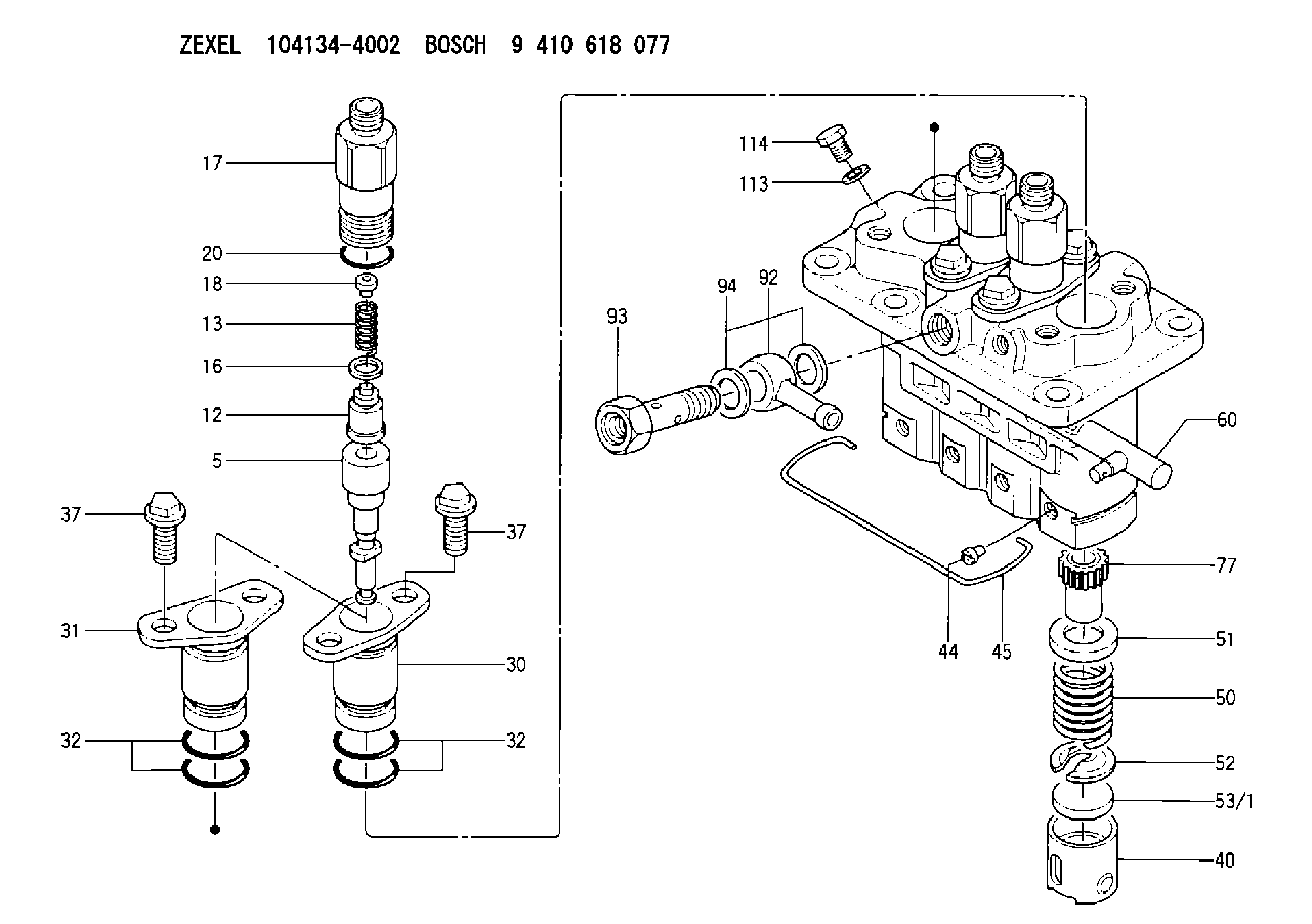
| 5. | [4] | 140163-2420 | PLUNGER-AND-BARREL ASSY |
| 12. | [4] | 140110-3720 | DELIVERY-VALVE ASSEMBLY |
| 13. | [4] | 140112-1700 | COMPRESSION SPRING |
| 16. | [4] | 140115-1400 | GASKET |
| 17. | [4] | 140116-7600 | FITTING |
| 18. | [4] | 140117-1800 | SLOTTED WASHER |
| 20. | [4] | 016500-1520 | O-RING |
| 30. | [3] | 140131-0521 | FLANGE BUSHING |
| 31. | [1] | 140131-1021 | FLANGE BUSHING |
| 32. | [8] | 016550-1920 | O-RING |
| 32. | [8] | 016550-1920 | O-RING |
| 37. | [8] | 140124-0200 | BLEEDER SCREW |
| 37. | [8] | 140124-0200 | BLEEDER SCREW |
| 40. | [4] | 140200-1620 | TAPPET |
| 44. | [4] | 140212-0300 | BEARING PIN |
| 45. | [1] | 140213-1500 | LOCKING WASHER |
| 50. | [4] | 140215-1900 | COMPRESSION SPRING |
| 51. | [4] | 140216-0800 | SLOTTED WASHER |
| 52. | [4] | 140217-2200 | SLOTTED WASHER |
| 53/1. | [1] | 140217-5000 | PLATE D19T2.60 |
| 53/1. | [1] | 140217-5100 | PLATE D19T2.65 |
| 53/1. | [1] | 140217-5200 | PLATE D19T2.70 |
| 53/1. | [1] | 140217-5300 | PLATE D19T2.75 |
| 53/1. | [1] | 140217-5400 | PLATE D19T2.80 |
| 53/1. | [1] | 140217-5500 | PLATE D19T2.85 |
| 53/1. | [1] | 140217-5600 | PLATE D19T2.90 |
| 53/1. | [1] | 140217-5700 | PLATE D19T2.95 |
| 53/1. | [1] | 140217-5800 | PLATE D19T3.00 |
| 53/1. | [1] | 140217-5900 | PLATE D19T3.05 |
| 53/1. | [1] | 140217-6000 | PLATE D19T3.10 |
| 53/1. | [1] | 140217-6100 | PLATE D19T3.15 |
| 53/1. | [1] | 140217-6200 | PLATE D19T3.20 |
| 53/1. | [1] | 140217-6300 | PLATE D19T3.25 |
| 53/1. | [1] | 140217-6400 | PLATE D19T3.30 |
| 53/1. | [1] | 140217-6500 | PLATE D19T3.35 |
| 53/1. | [1] | 140217-6600 | PLATE D19T3.40 |
| 53/1. | [1] | 140217-6700 | PLATE D19T3.45 |
| 53/1. | [1] | 140217-6800 | PLATE D19T3.50 |
| 53/1. | [1] | 140217-6900 | PLATE D19T3.55 |
| 53/1. | [1] | 140217-7000 | PLATE D19T3.60 |
| 53/1. | [1] | 140217-7100 | PLATE D19T3.65 |
| 53/1. | [1] | 140217-7200 | PLATE D19T3.70 |
| 53/1. | [1] | 140217-7300 | PLATE D19T3.75 |
| 53/1. | [1] | 140217-7400 | PLATE D19T3.80 |
| 53/1. | [1] | 140217-7500 | PLATE D19T3.85 |
| 53/1. | [1] | 140217-7600 | PLATE D19T3.90 |
| 53/1. | [1] | 140217-7700 | PLATE D19T3.95 |
| 53/1. | [1] | 140217-7800 | PLATE D19T4.00 |
| 53/1. | [1] | 140217-7900 | PLATE D19T4.05 |
| 53/1. | [1] | 140217-8000 | PLATE D19T4.10 |
| 53/1. | [1] | 140253-2000 | PLATE |
| 53/1. | [1] | 140253-2100 | PLATE |
| 53/1. | [1] | 140253-2200 | PLATE |
| 53/1. | [1] | 140253-2300 | PLATE |
| 53/1. | [1] | 140253-2400 | PLATE |
| 53/1. | [1] | 140253-2500 | PLATE |
| 53/1. | [1] | 140253-2600 | PLATE |
| 53/1. | [1] | 140253-2700 | PLATE |
| 53/1. | [1] | 140253-2800 | PLATE |
| 53/1. | [1] | 140253-2900 | PLATE |
| 53/1. | [1] | 140253-3000 | PLATE |
| 53/1. | [1] | 140253-3100 | PLATE |
| 53/1. | [1] | 140253-3200 | PLATE |
| 53/1. | [1] | 140253-3300 | PLATE |
| 53/1. | [1] | 140253-3400 | PLATE |
| 53/1. | [1] | 140253-3500 | PLATE |
| 53/1. | [1] | 140253-3600 | PLATE |
| 53/1. | [1] | 140253-3700 | PLATE |
| 53/1. | [1] | 140253-3800 | PLATE |
| 53/1. | [1] | 140253-3900 | PLATE |
| 53/1. | [1] | 140253-4000 | PLATE |
| 53/1. | [1] | 140253-4100 | PLATE |
| 53/1. | [1] | 140253-4200 | PLATE |
| 53/1. | [1] | 140253-4300 | PLATE |
| 53/1. | [1] | 140253-4400 | PLATE |
| 53/1. | [1] | 140253-4500 | PLATE |
| 53/1. | [1] | 140253-4600 | PLATE |
| 53/1. | [1] | 140253-4700 | PLATE |
| 53/1. | [1] | 140253-4800 | PLATE |
| 53/1. | [1] | 140253-4900 | PLATE |
| 60. | [1] | 140243-5620 | CONTROL RACK |
| 77. | [4] | 140241-2700 | CONTROL SLEEVE |
| 92. | [1] | 029711-2050 | INLET UNION |
| 93. | [1] | 140402-1300 | EYE BOLT |
| 94. | [2] | 026512-1540 | GASKET D15.4&12.2T1.50 |
| 113. | [1] | 026508-1240 | GASKET D11.9&8.2T1 |
| 114. | [1] | 140420-1400 | BLEEDER SCREW |
Include in #2:
104134-4002
as INJECTION-PUMP ASSEMBLY
Cross reference number
Zexel num
Bosch num
Firm num
Name
131017541 ISHIKAWAJIMA-S
FUEL-INJECTION PUMP
* K
* K
Information:
Before any service work is done on the fuel system, the outer surface of the injection pump housing must be clean.
1. Disconnect two fuel lines (1) from the fuel transfer pump. 2. Remove two bolts (3) and fuel transfer pump (2).Install Fuel Transfer Pump
1. Put fuel transfer pump (1) in position and install the two bolts that hold it to the fuel pump housing. 2. Connect two lines (2) to the fuel transfer pump.Disassemble Fuel Transfer Pump
start by:a) remove fuel transfer pump 1. Remove bolts (1) that hold transfer pump cover (2) to transfer pump body (5).2. Remove bolts and clamps (4) from the tachometer drive adapter. Remove tachometer drive adapter (3) from the cover. 3. Remove lip type seal (6) from the cover. Remove plug and O-ring seal (7), seat (8), spring (9) and valve (10) from the cover. 4. Remove nut (14) on end of shaft (11) and remove gear (17) and key (12) from the shaft. Remove O-ring seal (13) and the shaft from the body (5).5. Remove idler gear (15) from shaft (16).6. Remove the bearings and the two lip type seals from the body.7. Remove the check valve and shaft (16) from the body.Assemble Fuel Transfer Pump
1. Clean the openings (ports) for the fuel passage in body (3).2. Install shaft (1) and check valve (2) in the body with tooling (A).3. Install smaller bearing (4) in the body with tooling (B). Install the bearing until it is even with the machined surface of the body. 4. Install seal (5) in the body with tooling (C). Install the seal until it is .969 in. (24.6 mm) from the top surface of the body and with the lip toward bearing (4) as shown.5. Install seal (6) in body (3) with tooling (D). Install the seal until it is .563 in. (14.3 mm) from the top surface of the body and with the lip toward the top surface of body (3) as shown. 6. Install the large bearing in body (3) with tooling (E). Install the bearing even with the outside surface of the body. 7. Install the seal in cover (7) with tooling (C). Install the seal with the lip toward the inside of the cover and until it is .750 in. (19.1 mm) below the outside surface of the cover.8. Install the fuel bypass valve, the valve, spring, seal, O-ring seal and plug (14) in the cover. Tighten the plug to a torque of 27 3 lb.ft. (38 4 N m).9. Install shaft (9) in the body. Install gear (13) on the shaft to make an alignment with the gear on the shaft.10. Put 7M7260 Liquid Gasket Material on surface of cover (8). Install the cover on the body.
Do not let liquid gasket material enter the pump.
11. Install the six bolts that hold the cover (7) to the body. Install the O-ring seal to the body. The shaft must turn freely after the bolts that hold the cover in position are tightened.12.