Information fuel-injection pump
BOSCH
9 410 617 047
9410617047
ZEXEL
104134-4001
1041344001
Rating:
Compare Prices: .
As an associate, we earn commssions on qualifying purchases through the links below

Original Fuel Injection Pump Compatible With Kubota Perkins Engine 104134-4001 Excavator Engine Replacement Parts
YERCBX Lightweight design: Utilizing lightweight materials to reduce the weight of the vehicle || Enhance the engine's power output || Low-noise operation: Optimized internal structure and materials, resulting in low noise during operation || The key components have excellent wear resistance, extending the overall service life || Integrated design: Compact structure, small space occupation, and convenient for vehicle installation and layout.
YERCBX Lightweight design: Utilizing lightweight materials to reduce the weight of the vehicle || Enhance the engine's power output || Low-noise operation: Optimized internal structure and materials, resulting in low noise during operation || The key components have excellent wear resistance, extending the overall service life || Integrated design: Compact structure, small space occupation, and convenient for vehicle installation and layout.

New Fuel Injection Pump Compatible For Kubota Perkins Engine 104134-4001 Excavator Engine Replacement Parts
TBEFQVAW Lightweight design: effectively reduces vehicle load, improves fuel economy, and facilitates installation and handling || Multi specification adaptation: providing multiple flow specifications and models to meet the needs of different displacement engines || Adaptive installation: Standardized interface design, compatible with 95% of mainstream engine models, no need for complex modifications || Anti corrosion coating: The surface of key components is covered with anti-corrosion coating, which is not afraid of humid coastal environments and harsh weather conditions || New Fuel Injection Pump Compatible For Kubota Perkins Engine 104134-4001 Excavator Engine Replacement Parts
TBEFQVAW Lightweight design: effectively reduces vehicle load, improves fuel economy, and facilitates installation and handling || Multi specification adaptation: providing multiple flow specifications and models to meet the needs of different displacement engines || Adaptive installation: Standardized interface design, compatible with 95% of mainstream engine models, no need for complex modifications || Anti corrosion coating: The surface of key components is covered with anti-corrosion coating, which is not afraid of humid coastal environments and harsh weather conditions || New Fuel Injection Pump Compatible For Kubota Perkins Engine 104134-4001 Excavator Engine Replacement Parts

You can express buy:
USD 393.12
01-07-2025
01-07-2025
China Made New Fuel Injection Pump Head 104134-4001 Fits for Perkins
Components :
| 0. | INJECTION-PUMP ASSEMBLY | 104134-4001 |
| 1. | _ | |
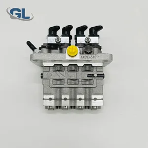
| 2. | FUEL INJECTION PUMP | |
| 3. | NUMBER PLATE | |
| 4. | _ | |
| 5. | CAPSULE | |
| 6. | ADJUSTING DEVICE | |
| 7. | NOZZLE AND HOLDER ASSY | 105141-2200 |
| 8. | Nozzle and Holder | |
| 9. | Open Pre:MPa(Kqf/cm2) | 11.8{120} |
| 10. | NOZZLE-HOLDER | 105071-0640 |
| 11. | NOZZLE | 105000-1010 |
Scheme ###:
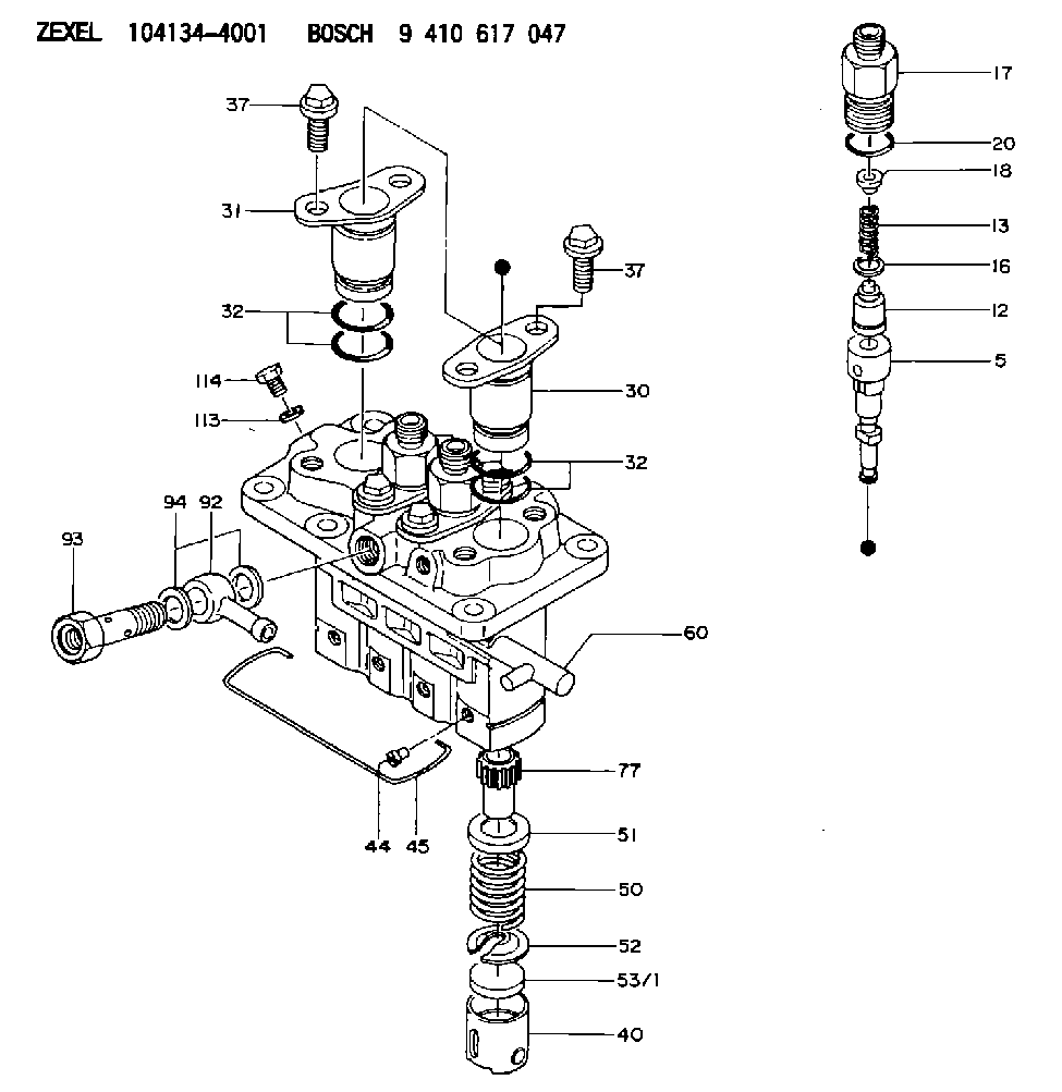
| 5. | [4] | 140153-5320 | PLUNGER-AND-BARREL ASSY |
| 12. | [4] | 140110-3720 | DELIVERY-VALVE ASSEMBLY |
| 13. | [4] | 140112-1700 | COMPRESSION SPRING |
| 16. | [4] | 140115-1400 | GASKET |
| 17. | [4] | 140116-7600 | FITTING |
| 18. | [4] | 140117-1800 | SLOTTED WASHER |
| 20. | [4] | 016500-1520 | O-RING |
| 30. | [3] | 140131-0521 | FLANGE BUSHING |
| 31. | [1] | 140131-1021 | FLANGE BUSHING |
| 32. | [8] | 016550-1920 | O-RING |
| 32. | [8] | 016550-1920 | O-RING |
| 37. | [8] | 140124-0200 | BLEEDER SCREW |
| 37. | [8] | 140124-0200 | BLEEDER SCREW |
| 40. | [4] | 140200-1620 | TAPPET |
| 44. | [4] | 140212-0300 | BEARING PIN |
| 45. | [1] | 140213-1500 | LOCKING WASHER |
| 50. | [4] | 140215-1900 | COMPRESSION SPRING |
| 51. | [4] | 140216-0800 | SLOTTED WASHER |
| 52. | [4] | 140217-2200 | SLOTTED WASHER |
| 53/1. | [1] | 140217-5000 | PLATE D19T2.60 |
| 53/1. | [1] | 140217-5100 | PLATE D19T2.65 |
| 53/1. | [1] | 140217-5200 | PLATE D19T2.70 |
| 53/1. | [1] | 140217-5300 | PLATE D19T2.75 |
| 53/1. | [1] | 140217-5400 | PLATE D19T2.80 |
| 53/1. | [1] | 140217-5500 | PLATE D19T2.85 |
| 53/1. | [1] | 140217-5600 | PLATE D19T2.90 |
| 53/1. | [1] | 140217-5700 | PLATE D19T2.95 |
| 53/1. | [1] | 140217-5800 | PLATE D19T3.00 |
| 53/1. | [1] | 140217-5900 | PLATE D19T3.05 |
| 53/1. | [1] | 140217-6000 | PLATE D19T3.10 |
| 53/1. | [1] | 140217-6100 | PLATE D19T3.15 |
| 53/1. | [1] | 140217-6200 | PLATE D19T3.20 |
| 53/1. | [1] | 140217-6300 | PLATE D19T3.25 |
| 53/1. | [1] | 140217-6400 | PLATE D19T3.30 |
| 53/1. | [1] | 140217-6500 | PLATE D19T3.35 |
| 53/1. | [1] | 140217-6600 | PLATE D19T3.40 |
| 53/1. | [1] | 140217-6700 | PLATE D19T3.45 |
| 53/1. | [1] | 140217-6800 | PLATE D19T3.50 |
| 53/1. | [1] | 140217-6900 | PLATE D19T3.55 |
| 53/1. | [1] | 140217-7000 | PLATE D19T3.60 |
| 53/1. | [1] | 140217-7100 | PLATE D19T3.65 |
| 53/1. | [1] | 140217-7200 | PLATE D19T3.70 |
| 53/1. | [1] | 140217-7300 | PLATE D19T3.75 |
| 53/1. | [1] | 140217-7400 | PLATE D19T3.80 |
| 53/1. | [1] | 140217-7500 | PLATE D19T3.85 |
| 53/1. | [1] | 140217-7600 | PLATE D19T3.90 |
| 53/1. | [1] | 140217-7700 | PLATE D19T3.95 |
| 53/1. | [1] | 140217-7800 | PLATE D19T4.00 |
| 53/1. | [1] | 140217-7900 | PLATE D19T4.05 |
| 53/1. | [1] | 140217-8000 | PLATE D19T4.10 |
| 53/1. | [1] | 140253-2000 | PLATE |
| 53/1. | [1] | 140253-2100 | PLATE |
| 53/1. | [1] | 140253-2200 | PLATE |
| 53/1. | [1] | 140253-2300 | PLATE |
| 53/1. | [1] | 140253-2400 | PLATE |
| 53/1. | [1] | 140253-2500 | PLATE |
| 53/1. | [1] | 140253-2600 | PLATE |
| 53/1. | [1] | 140253-2700 | PLATE |
| 53/1. | [1] | 140253-2800 | PLATE |
| 53/1. | [1] | 140253-2900 | PLATE |
| 53/1. | [1] | 140253-3000 | PLATE |
| 53/1. | [1] | 140253-3100 | PLATE |
| 53/1. | [1] | 140253-3200 | PLATE |
| 53/1. | [1] | 140253-3300 | PLATE |
| 53/1. | [1] | 140253-3400 | PLATE |
| 53/1. | [1] | 140253-3500 | PLATE |
| 53/1. | [1] | 140253-3600 | PLATE |
| 53/1. | [1] | 140253-3700 | PLATE |
| 53/1. | [1] | 140253-3800 | PLATE |
| 53/1. | [1] | 140253-3900 | PLATE |
| 53/1. | [1] | 140253-4000 | PLATE |
| 53/1. | [1] | 140253-4100 | PLATE |
| 53/1. | [1] | 140253-4200 | PLATE |
| 53/1. | [1] | 140253-4300 | PLATE |
| 53/1. | [1] | 140253-4400 | PLATE |
| 53/1. | [1] | 140253-4500 | PLATE |
| 53/1. | [1] | 140253-4600 | PLATE |
| 53/1. | [1] | 140253-4700 | PLATE |
| 53/1. | [1] | 140253-4800 | PLATE |
| 53/1. | [1] | 140253-4900 | PLATE |
| 60. | [1] | 140243-5620 | CONTROL RACK |
| 77. | [4] | 140241-2700 | CONTROL SLEEVE |
| 92. | [1] | 029711-2050 | INLET UNION |
| 93. | [1] | 140402-1300 | EYE BOLT |
| 94. | [2] | 026512-1540 | GASKET D15.4&12.2T1.50 |
| 113. | [1] | 026508-1240 | GASKET D11.9&8.2T1 |
| 114. | [1] | 140420-1400 | BLEEDER SCREW |
Include in #1:
101602-1300
as _
Include in #2:
104134-4001
as INJECTION-PUMP ASSEMBLY
Cross reference number
Zexel num
Bosch num
Firm num
Name
Information:
Before any service work is done on the fuel system, the outer surface of the fuel injection pump housing must be clean.
1. Cut governor safety wire (1).2. Disconnect line (3) from the fuel ratio control.3. Remove the two bolts and fuel ratio control (2).Install Fuel Ratio Control
1. Put fuel ratio control in position. Make an alignment of opening (slot) (2) with the plunger in the fuel ratio control.2. Use 9S3263 Thread Lock and install the two bolts that hold fuel ratio control (1) to the governor plate. 3. Connect line (3) to the fuel ratio control.4. Install a new lockwire and seal. See FUEL RACK SETTING in TESTING AND ADJUSTING.
The lockwire and seal must be installed in order to validate the warranty.
Disassemble Fuel Ratio Control
start by:a) remove fuel ratio control 1. Remove two bolts (1) and cover (2). 2. Remove valve assembly (3).3. Remove seal (4) and the O-ring seal from the valve assembly.4. Remove retainer (5) and two springs (6). 5. Remove the three bolts from the cover. Remove cover (12) and gasket (11).6. Remove valve (13), diaphragm, (8), retainer (9) and spring (10).7. Remove pin (14) from valve (13).8. Remove cover (7) from the valve.Assemble Fuel Ratio Control
1. Put clean SAE 30 oil on the seal. Install seal (1) in cover (2) with the lip of the seal toward the inside of the cover. 2. Install valve (3) in cover (2).3. Install the pin that holds the cover on the valve. 4. Install the spring and the retainer in cover (6).5. Install diaphragm (5) on the valve assembly (4) and in the cover.6. Install cover (8). Install three bolts (7) that hold the cover in position. 7. Put clean SAE 30 oil on the seal and the ring seal. Install seals (11) on valve.8. Install two springs (12), retainer (13) and valve assembly (10).9. Install housing (9) and the bolts.
Correct adjustment must be made to fuel ratio control before installation. See ADJUSTMENT OF AIR FUEL RATIO CONTROL in TESTING AND ADJUSTING.
end by:a) install fuel ratio control