Information fuel-injection pump
BOSCH
9 410 618 461
9410618461
ZEXEL
104134-3071
1041343071
ISHIKAWAJIMA-S
131017821
131017821

Rating:
Compare Prices: .
As an associate, we earn commssions on qualifying purchases through the links below

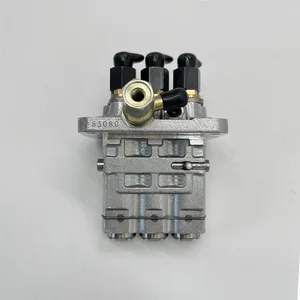
Nayuank Fuel Injection Pump 104134-3071 131017821 9410618461 Fits For Perkins Engine 400C Fits For JCB 803
Nayuank Part Name: Fuel Injection Pump || Part Number: 104134-3071 131017821 9410618461 Note: Please check the fitment carefully before purchase. Or just tell us the part number you need. || Engine Model: 400C || Applicable: Fits For JCB 803 || Fits For Perkins Engine 400C
Nayuank Part Name: Fuel Injection Pump || Part Number: 104134-3071 131017821 9410618461 Note: Please check the fitment carefully before purchase. Or just tell us the part number you need. || Engine Model: 400C || Applicable: Fits For JCB 803 || Fits For Perkins Engine 400C

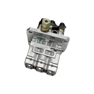
Nayuank Fuel Injection Pump 104134-3071 9410618461 131017821 Fits For Perkins Engine 400C 403C-15 Fits For New Holland Tractor TC30 Mower MC35 MC28
Nayuank Part Name: Fuel Injection Pump || Part Number: 104134-3071 9410618461 131017821 Note: Please check the fitment carefully before purchase. Or just tell us the part number you need. || Engine Model: 403C-15 || Applicable: Fits For Perkins Engine 400C 403C-15 || Fits For New Holland Tractor TC30 Mower MC35 MC28
Nayuank Part Name: Fuel Injection Pump || Part Number: 104134-3071 9410618461 131017821 Note: Please check the fitment carefully before purchase. Or just tell us the part number you need. || Engine Model: 403C-15 || Applicable: Fits For Perkins Engine 400C 403C-15 || Fits For New Holland Tractor TC30 Mower MC35 MC28
You can express buy:
USD 349.25
22-06-2025
22-06-2025
China Made New Fuel Injection Pump Head 131017821 104134-3071 Fits for Perkins
USD 1822.38
14-06-2025
14-06-2025
D722 Diesel Fuel Pump New Engine Accessories Part Numbers 104135-3050 104135-3060 104135-3080 104134-3071 104135-3010
Images:
USD 694.49

[13-May-2025]
Components :
| 0. | INJECTION-PUMP ASSEMBLY | 104134-3071 |
| 1. | _ | |
| 2. | FUEL INJECTION PUMP | |
| 3. | NUMBER PLATE | |
| 4. | _ | |
| 5. | CAPSULE | |
| 6. | ADJUSTING DEVICE | |
| 7. | NOZZLE AND HOLDER ASSY | 105148-1170 |
| 8. | Nozzle and Holder | |
| 9. | Open Pre:MPa(Kqf/cm2) | 14.7(150) |
| 10. | NOZZLE-HOLDER | 105078-0100 |
| 11. | NOZZLE | 105007-1170 |
Scheme ###:
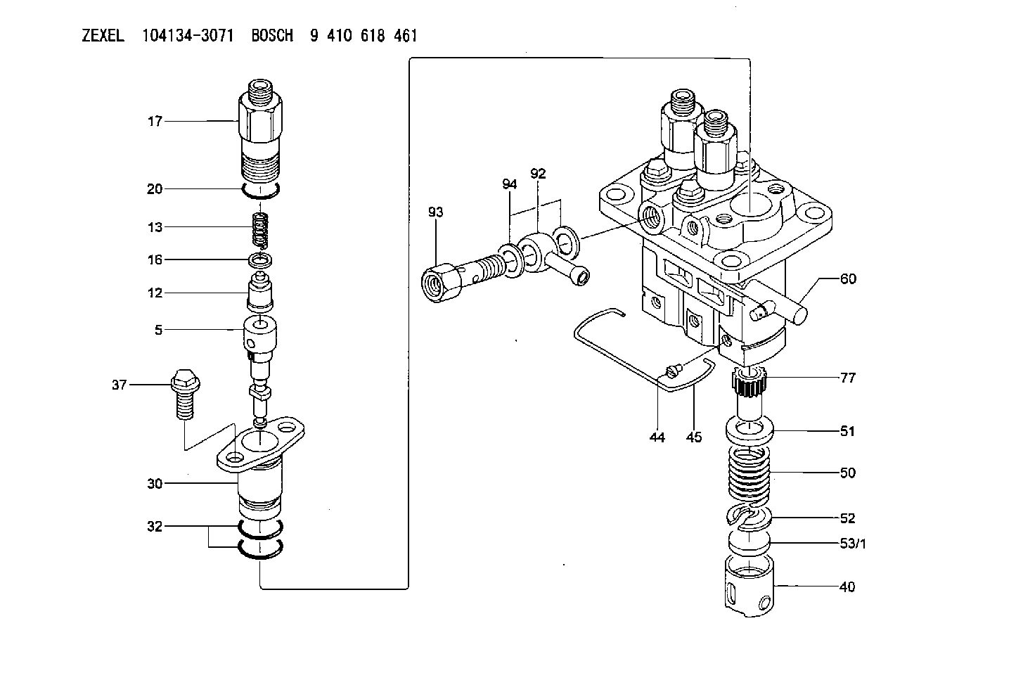
| 5. | [3] | 140163-2220 | PLUNGER-AND-BARREL ASSY |
| 12. | [3] | 140110-3620 | DELIVERY-VALVE ASSEMBLY |
| 13. | [3] | 140112-2900 | COMPRESSION SPRING |
| 16. | [3] | 140115-1400 | GASKET |
| 17. | [3] | 140116-7520 | FITTING |
| 20. | [3] | 140118-0301 | O-RING |
| 30. | [3] | 140131-0521 | FLANGE BUSHING |
| 32. | [6] | 140118-0201 | O-RING |
| 37. | [6] | 140124-0200 | BLEEDER SCREW |
| 40. | [3] | 140200-2620 | TAPPET |
| 44. | [3] | 140212-0300 | BEARING PIN |
| 45. | [1] | 140213-1400 | LOCKING WASHER |
| 50. | [3] | 140215-1900 | COMPRESSION SPRING |
| 51. | [3] | 140216-0800 | SLOTTED WASHER |
| 52. | [3] | 140217-2200 | SLOTTED WASHER |
| 53/1. | [1] | 140217-5000 | PLATE D19T2.60 |
| 53/1. | [1] | 140217-5100 | PLATE D19T2.65 |
| 53/1. | [1] | 140217-5200 | PLATE D19T2.70 |
| 53/1. | [1] | 140217-5300 | PLATE D19T2.75 |
| 53/1. | [1] | 140217-5400 | PLATE D19T2.80 |
| 53/1. | [1] | 140217-5500 | PLATE D19T2.85 |
| 53/1. | [1] | 140217-5600 | PLATE D19T2.90 |
| 53/1. | [1] | 140217-5700 | PLATE D19T2.95 |
| 53/1. | [1] | 140217-5800 | PLATE D19T3.00 |
| 53/1. | [1] | 140217-5900 | PLATE D19T3.05 |
| 53/1. | [1] | 140217-6000 | PLATE D19T3.10 |
| 53/1. | [1] | 140217-6100 | PLATE D19T3.15 |
| 53/1. | [1] | 140217-6200 | PLATE D19T3.20 |
| 53/1. | [1] | 140217-6300 | PLATE D19T3.25 |
| 53/1. | [1] | 140217-6400 | PLATE D19T3.30 |
| 53/1. | [1] | 140217-6500 | PLATE D19T3.35 |
| 53/1. | [1] | 140217-6600 | PLATE D19T3.40 |
| 53/1. | [1] | 140217-6700 | PLATE D19T3.45 |
| 53/1. | [1] | 140217-6800 | PLATE D19T3.50 |
| 53/1. | [1] | 140217-6900 | PLATE D19T3.55 |
| 53/1. | [1] | 140217-7000 | PLATE D19T3.60 |
| 53/1. | [1] | 140217-7100 | PLATE D19T3.65 |
| 53/1. | [1] | 140217-7200 | PLATE D19T3.70 |
| 53/1. | [1] | 140217-7300 | PLATE D19T3.75 |
| 53/1. | [1] | 140217-7400 | PLATE D19T3.80 |
| 53/1. | [1] | 140217-7500 | PLATE D19T3.85 |
| 53/1. | [1] | 140217-7600 | PLATE D19T3.90 |
| 53/1. | [1] | 140217-7700 | PLATE D19T3.95 |
| 53/1. | [1] | 140217-7800 | PLATE D19T4.00 |
| 53/1. | [1] | 140217-7900 | PLATE D19T4.05 |
| 53/1. | [1] | 140217-8000 | PLATE D19T4.10 |
| 53/1. | [1] | 140253-2000 | PLATE |
| 53/1. | [1] | 140253-2100 | PLATE |
| 53/1. | [1] | 140253-2200 | PLATE |
| 53/1. | [1] | 140253-2300 | PLATE |
| 53/1. | [1] | 140253-2400 | PLATE |
| 53/1. | [1] | 140253-2500 | PLATE |
| 53/1. | [1] | 140253-2600 | PLATE |
| 53/1. | [1] | 140253-2700 | PLATE |
| 53/1. | [1] | 140253-2800 | PLATE |
| 53/1. | [1] | 140253-2900 | PLATE |
| 53/1. | [1] | 140253-3000 | PLATE |
| 53/1. | [1] | 140253-3100 | PLATE |
| 53/1. | [1] | 140253-3200 | PLATE |
| 53/1. | [1] | 140253-3300 | PLATE |
| 53/1. | [1] | 140253-3400 | PLATE |
| 53/1. | [1] | 140253-3500 | PLATE |
| 53/1. | [1] | 140253-3600 | PLATE |
| 53/1. | [1] | 140253-3700 | PLATE |
| 53/1. | [1] | 140253-3800 | PLATE |
| 53/1. | [1] | 140253-3900 | PLATE |
| 53/1. | [1] | 140253-4000 | PLATE |
| 53/1. | [1] | 140253-4100 | PLATE |
| 53/1. | [1] | 140253-4200 | PLATE |
| 53/1. | [1] | 140253-4300 | PLATE |
| 53/1. | [1] | 140253-4400 | PLATE |
| 53/1. | [1] | 140253-4500 | PLATE |
| 53/1. | [1] | 140253-4600 | PLATE |
| 53/1. | [1] | 140253-4700 | PLATE |
| 53/1. | [1] | 140253-4800 | PLATE |
| 53/1. | [1] | 140253-4900 | PLATE |
| 60. | [1] | 140243-5520 | CONTROL RACK |
| 77. | [3] | 140241-2700 | CONTROL SLEEVE |
| 92. | [1] | 029711-2050 | INLET UNION |
| 93. | [1] | 140402-1300 | EYE BOLT |
| 94. | [2] | 026512-1540 | GASKET D15.4&12.2T1.50 |
Include in #2:
104134-3071
as INJECTION-PUMP ASSEMBLY
Cross reference number
Zexel num
Bosch num
Firm num
Name
Information:
8. Remove O-ring seal (10), the thrust washer and the bearing from the adapter with tool (A).9. Remove bolts (12) from the cover. Remove cover (11) and the gasket from the crankcase. 10. Bend down the lock on lock straps (13). Remove bolts (14) from the bearing caps.11. Put identification on the bearing caps for correct installation with the connecting rod. Remove the bearing caps. 12. Remove pistons (15) from the crankcase through the top of the cylinders.13. Remove crankshaft (16) from the crankcase. Remove the key from the crankshaft. 14. Remove end cover (17) from the crankcase. Remove the O-ring seal, the thrust washer and the bearing.15. Remove cover (18), the gasket and the strainer from the air inlet opening. 16. Remove inlet valves (20) from their guides (21). Remove the inlet valve guides from around the inlet valve seats.
Be careful not to cause damage to the inlet valve seats.
17. Remove (unloader) spring (19), spring saddle (22) and the spring seat from the housing with needle nose pliers. 18. Remove (unloader) plunger (24) and guides (25) from the housing. Remove the guides from the plungers to plungers.19. To remove (unloader) pistons (23) from the bore, put a cover over the inlet port, then blow air pressure in the governor mounting pad (unloader) port. 20. Remove lockpin (27) that holds rod pin (26) in the piston. Remove the pin from connecting rod (28). 21. Remove the piston rings from piston (30). Remove two compression rings (29), the oil ring and the expander ring with tool (B).22. Remove the bearings from the connecting rod and the connecting rod cap. 23. Remove the piston pin bushing with tool (C).24. Remove the small seal rings from both ends of the housing.25. Clean all the oil passages through the housing, the crankshaft, the end cover and the adapter.Assemble Air Compressor
1. Check (unloader) bore bushings (1) for damage and wear. If these bushings need replacement, remove the bushing by the use of a 1/8 in. (3.18 mm) pipe threaded tap. Then install a 1/8 in. (3.18 mm) pipe threaded rod and pull the bushing straight up and out.2. Check the cylinder bores in the crankcase housing for damages (scored or out of round). Measure the cylinder bore in several places. If the measurement difference is more than .001 in. (0.03 mm) or taper is more than .002 (0.05 mm), the cylinder bore must be made larger (rebored or honed oversize). See SPECIFICATIONS.3. Install seal rings (3) in both ends of the crankcase housing.4. Install the new (unloader) pistons in their bore.
Be careful not to cause damage to the O-ring seals or the spiral rings.
5. Put the unloader plungers in their guides. Install the plunger and guide as a unit (6) to the crankcase housing and on top of the pistons. Install the unloader spring seat in the crankcase housing.6. Put saddle (4) in position between the unloader piston guides. Install (unloader) spring (8). Make sure it makes a seat on the spring seats