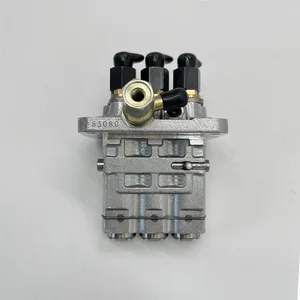
Information fuel-injection pump
BOSCH
9 410 618 460
9410618460
ZEXEL
104134-3051
1041343051
ISHIKAWAJIMA-H
131017701
131017701

Rating:
Compare Prices: .
As an associate, we earn commssions on qualifying purchases through the links below

BNUSLO Fuel Injection Pump 131017700 104134-3051 Replacement for New Holland TC33D TC29D TC33DA
BNUSLO Condition: New Replacement Fuel Injection Pump || Part Number: SBA131017700, 131017700, 87763378, 9410618460, 9410617211, 104134-3050, 131017701, 104134-3051 || Application: Replacement for New Holland Tractor: TC33D, TC29D, TC33DA, TC29DA, TC25, TC25D, TC33, TC29; Mower: MC28, MC35 || Package Included: 1PC || Please check the product picture and the part number carefully before you order it. If you are not sure, please leave us a message, we are here to help. Thanks a lot.
BNUSLO Condition: New Replacement Fuel Injection Pump || Part Number: SBA131017700, 131017700, 87763378, 9410618460, 9410617211, 104134-3050, 131017701, 104134-3051 || Application: Replacement for New Holland Tractor: TC33D, TC29D, TC33DA, TC29DA, TC25, TC25D, TC33, TC29; Mower: MC28, MC35 || Package Included: 1PC || Please check the product picture and the part number carefully before you order it. If you are not sure, please leave us a message, we are here to help. Thanks a lot.

Fuel Injection Pump for New Holland Tractor MC28 TC25 TC25D TC29 TC29D TC29DA TC30 TC33 Case Tractor D25 D29 D33 DX25 DX29 DX33 9410618460 131017701 104134-3051
KoovDem Part Number: 131017701 104134-3051 9410618460 || Application:For New Holland Tractor MC28 TC25 TC25D TC29 TC29D TC30 TC33 || The vehicle application is suitable for use with Case Tractor models D25, D29, D33, DX25, DX29, and DX33. || for verification. This will help ensure that you receive the correct part for your vehicle. It is important to double check the accuracy of the part numbers to avoid any delays or inconvenience. Thank you for your attention to detail and for choosing our services. || Service: We offer a 5-month warranty on all products, along with 24-hour customer support for any inquiries or issues. If you have any questions regarding the product, please don't hesitate to reach out to us via email.
KoovDem Part Number: 131017701 104134-3051 9410618460 || Application:For New Holland Tractor MC28 TC25 TC25D TC29 TC29D TC30 TC33 || The vehicle application is suitable for use with Case Tractor models D25, D29, D33, DX25, DX29, and DX33. || for verification. This will help ensure that you receive the correct part for your vehicle. It is important to double check the accuracy of the part numbers to avoid any delays or inconvenience. Thank you for your attention to detail and for choosing our services. || Service: We offer a 5-month warranty on all products, along with 24-hour customer support for any inquiries or issues. If you have any questions regarding the product, please don't hesitate to reach out to us via email.

IMIFAFTAbT SBA131017700 SBA131017701 104134-3051 Fuel Injection Pump for New Holland TC25D TC29D TC30 TC33D MC28 MC35 for Case D25 D29 D33 DX25 DX29 DX33
IMIFAFTAbT Part Name:Fuel Injection Pump SBA131017700 SBA131017701 104134-3051 || Part Number:SBA131017700 SBA131017701 104134-3051 || APPlication: Compatible with New Holland TC25D TC29D TC30 TC33D MC28 MC35 for Case D25 D29 D33 DX25 DX29 DX33 || If you are not sure if the product is suitable please leave us a message and send us your original || product picture and part number and we will send the correct part after confirmation
IMIFAFTAbT Part Name:Fuel Injection Pump SBA131017700 SBA131017701 104134-3051 || Part Number:SBA131017700 SBA131017701 104134-3051 || APPlication: Compatible with New Holland TC25D TC29D TC30 TC33D MC28 MC35 for Case D25 D29 D33 DX25 DX29 DX33 || If you are not sure if the product is suitable please leave us a message and send us your original || product picture and part number and we will send the correct part after confirmation
You can express buy:
USD 349.25
25-05-2025
25-05-2025
China Made New Fuel Injection Pump Head 131017701 104134-3051 Fits for Perkins
Components :
| 0. | INJECTION-PUMP ASSEMBLY | 104134-3051 |
| 1. | _ | |
| 2. | FUEL INJECTION PUMP | |
| 3. | NUMBER PLATE | |
| 4. | _ | |
| 5. | CAPSULE | |
| 6. | ADJUSTING DEVICE | |
| 7. | NOZZLE AND HOLDER ASSY | 105148-1210 |
| 8. | Nozzle and Holder | |
| 9. | Open Pre:MPa(Kqf/cm2) | 11.8(120) |
| 10. | NOZZLE-HOLDER | 105078-0100 |
| 11. | NOZZLE | 105007-1170 |
Scheme ###:
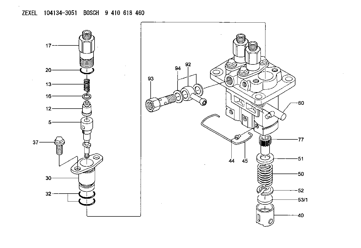
| 5. | [3] | 140163-0820 | PLUNGER-AND-BARREL ASSY |
| 12. | [3] | 140110-3620 | DELIVERY-VALVE ASSEMBLY |
| 13. | [3] | 140112-2900 | COMPRESSION SPRING |
| 16. | [3] | 140115-1400 | GASKET |
| 17. | [3] | 140116-7520 | FITTING |
| 20. | [3] | 140118-0301 | O-RING |
| 30. | [3] | 140131-0521 | FLANGE BUSHING |
| 32. | [6] | 140118-0201 | O-RING |
| 37. | [6] | 140124-0200 | BLEEDER SCREW |
| 40. | [3] | 140200-2620 | TAPPET |
| 44. | [3] | 140212-0300 | BEARING PIN |
| 45. | [1] | 140213-1400 | LOCKING WASHER |
| 50. | [3] | 140215-1900 | COMPRESSION SPRING |
| 51. | [3] | 140216-0800 | SLOTTED WASHER |
| 52. | [3] | 140217-2200 | SLOTTED WASHER |
| 53/1. | [1] | 140217-5000 | PLATE D19T2.60 |
| 53/1. | [1] | 140217-5100 | PLATE D19T2.65 |
| 53/1. | [1] | 140217-5200 | PLATE D19T2.70 |
| 53/1. | [1] | 140217-5300 | PLATE D19T2.75 |
| 53/1. | [1] | 140217-5400 | PLATE D19T2.80 |
| 53/1. | [1] | 140217-5500 | PLATE D19T2.85 |
| 53/1. | [1] | 140217-5600 | PLATE D19T2.90 |
| 53/1. | [1] | 140217-5700 | PLATE D19T2.95 |
| 53/1. | [1] | 140217-5800 | PLATE D19T3.00 |
| 53/1. | [1] | 140217-5900 | PLATE D19T3.05 |
| 53/1. | [1] | 140217-6000 | PLATE D19T3.10 |
| 53/1. | [1] | 140217-6100 | PLATE D19T3.15 |
| 53/1. | [1] | 140217-6200 | PLATE D19T3.20 |
| 53/1. | [1] | 140217-6300 | PLATE D19T3.25 |
| 53/1. | [1] | 140217-6400 | PLATE D19T3.30 |
| 53/1. | [1] | 140217-6500 | PLATE D19T3.35 |
| 53/1. | [1] | 140217-6600 | PLATE D19T3.40 |
| 53/1. | [1] | 140217-6700 | PLATE D19T3.45 |
| 53/1. | [1] | 140217-6800 | PLATE D19T3.50 |
| 53/1. | [1] | 140217-6900 | PLATE D19T3.55 |
| 53/1. | [1] | 140217-7000 | PLATE D19T3.60 |
| 53/1. | [1] | 140217-7100 | PLATE D19T3.65 |
| 53/1. | [1] | 140217-7200 | PLATE D19T3.70 |
| 53/1. | [1] | 140217-7300 | PLATE D19T3.75 |
| 53/1. | [1] | 140217-7400 | PLATE D19T3.80 |
| 53/1. | [1] | 140217-7500 | PLATE D19T3.85 |
| 53/1. | [1] | 140217-7600 | PLATE D19T3.90 |
| 53/1. | [1] | 140217-7700 | PLATE D19T3.95 |
| 53/1. | [1] | 140217-7800 | PLATE D19T4.00 |
| 53/1. | [1] | 140217-7900 | PLATE D19T4.05 |
| 53/1. | [1] | 140217-8000 | PLATE D19T4.10 |
| 53/1. | [1] | 140253-2000 | PLATE |
| 53/1. | [1] | 140253-2100 | PLATE |
| 53/1. | [1] | 140253-2200 | PLATE |
| 53/1. | [1] | 140253-2300 | PLATE |
| 53/1. | [1] | 140253-2400 | PLATE |
| 53/1. | [1] | 140253-2500 | PLATE |
| 53/1. | [1] | 140253-2600 | PLATE |
| 53/1. | [1] | 140253-2700 | PLATE |
| 53/1. | [1] | 140253-2800 | PLATE |
| 53/1. | [1] | 140253-2900 | PLATE |
| 53/1. | [1] | 140253-3000 | PLATE |
| 53/1. | [1] | 140253-3100 | PLATE |
| 53/1. | [1] | 140253-3200 | PLATE |
| 53/1. | [1] | 140253-3300 | PLATE |
| 53/1. | [1] | 140253-3400 | PLATE |
| 53/1. | [1] | 140253-3500 | PLATE |
| 53/1. | [1] | 140253-3600 | PLATE |
| 53/1. | [1] | 140253-3700 | PLATE |
| 53/1. | [1] | 140253-3800 | PLATE |
| 53/1. | [1] | 140253-3900 | PLATE |
| 53/1. | [1] | 140253-4000 | PLATE |
| 53/1. | [1] | 140253-4100 | PLATE |
| 53/1. | [1] | 140253-4200 | PLATE |
| 53/1. | [1] | 140253-4300 | PLATE |
| 53/1. | [1] | 140253-4400 | PLATE |
| 53/1. | [1] | 140253-4500 | PLATE |
| 53/1. | [1] | 140253-4600 | PLATE |
| 53/1. | [1] | 140253-4700 | PLATE |
| 53/1. | [1] | 140253-4800 | PLATE |
| 53/1. | [1] | 140253-4900 | PLATE |
| 60. | [1] | 140243-5520 | CONTROL RACK |
| 77. | [3] | 140241-2700 | CONTROL SLEEVE |
| 92. | [1] | 029711-2050 | INLET UNION |
| 93. | [1] | 140402-1300 | EYE BOLT |
| 94. | [2] | 026512-1540 | GASKET D15.4&12.2T1.50 |
Include in #1:
106673-2290
as _
Include in #2:
104134-3051
as INJECTION-PUMP ASSEMBLY
Cross reference number
Zexel num
Bosch num
Firm num
Name
Information:
start by:a) remove turbocharger 1. Put a mark at the location of the cartridge with respect to turbine housing (1) and compressor housing (3).2. Loosen clamps (2) and make a separation of the housings from the cartridge.
When the nut is loosened, do not put a side force on the shaft.
3. Put cartridge (5) in tooling (A) and remove nut (4). 4. Use a press to push shaft (7) out of compressor wheel (6) and the cartridge. 5. Remove seal ring (8) and shroud (9) from the shaft. 6. Remove sleeve (10) from the backplate. 7. Remove two seal rings (11) from the sleeve. 8. Bend the locks back and remove bolts (12) and backplate (13) from the cartridge. 9. Remove collar (14) and ring (15) from the cartridge. 10. Remove bearing (16) from the cartridge. 11. Remove sleeve (17) from the cartridge. 12. Remove washer (18) from the cartridge. 13. Remove snap ring (19) from the cartridge with tooling (B). 14. Use tool (B) to remove snap ring (20) and sleeve (21). 15. Remove washer (22) from the cartridge.16. Remove snap ring (23) with tool (B).Assemble Turbocharger (Airesearch TV8103)
1. Clean all parts thoroughly before the turbocharger is assembled. Put clean engine oil on all parts. 2. Install lower snap ring (2) with tool (A).3. Install washer (1) in the cartridge. 4. Put sleeve (4) in position and install snap ring (3) with tool (A). 5. Install snap ring (5) with tool (A). 6. Put the washer in position and install sleeve (6). 7. Put bearing (7) in position on the cartridge. Make an alignment of the dowels with the holes in the bearing. 8. Put seal (8) in position on the cartridge.9. Install collar (9) with large diameter up. 10. Put backplate (10) in position and install bolts (13) and the locks. Tighten bolts (13) to a torque of 90 10 lb.in. (10.2 1.1 N m). 11. Put seals (11) in position on the spacer. 12. Put spacer (12) in position with the small flat up. 13. Put shaft assembly (14) in position in tooling (B).14. Put 6V2055 High Vacuum Grease in groove and on seal (16). Install the seal.15. Install shroud (15). 16. Put cartridge assembly (18) in position on the shaft assembly.17. Put a small amount of oil on the threads of the shaft and on face of the compressor wheel under the nut.
Do not put a side force on the shaft when the nut is tightened.
18. Install compressor wheel (17) and the nut. Tighten the nut to a torque of 120 lb. in. (14 N m) to make a seat for the impeller against the spacer. 19. Loosen nut (19) and tighten it to a torque of 30 lb. in. (3 N m) plus 90°. 20. Check end play with tooling (C) as shown. See SPECIFICATIONS for the correct end play dimension. 21. Put the cartridge and clamps (20) in position on compressor housing (22). Install turbine housing (21) on the cartridge. 22.