Information fuel-injection pump
BOSCH
9 410 617 379
9410617379
ZEXEL
104132-6040
1041326040
M.BISHI-HI.-NAG
EZ40053
ez40053
Rating:
Components :
| 0. | INJECTION-PUMP ASSEMBLY | 104132-6040 |
| 1. | _ | |
| 2. | FUEL INJECTION PUMP | |
| 3. | NUMBER PLATE | |
| 4. | _ | |
| 5. | CAPSULE | |
| 6. | ADJUSTING DEVICE | |
| 7. | NOZZLE AND HOLDER ASSY | 105113-3070 |
| 8. | Nozzle and Holder | |
| 9. | Open Pre:MPa(Kqf/cm2) | 24.5{250} |
| 10. | NOZZLE-HOLDER | 105043-3020 |
| 11. | NOZZLE | 105011-9600 |
Scheme ###:
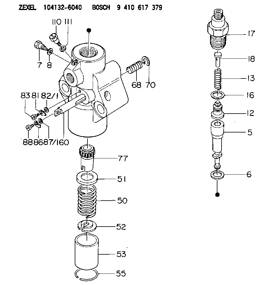
| 5. | [1] | 140153-2620 | PLUNGER-AND-BARREL ASSY |
| 6. | [1] | 029332-5040 | GASKET D30&25T0.2 |
| 7. | [1] | 140106-1400 | CAPSULE |
| 8. | [1] | 029330-8050 | GASKET |
| 12. | [1] | 140110-2020 | DELIVERY-VALVE ASSEMBLY |
| 13. | [1] | 140112-2100 | COMPRESSION SPRING |
| 16. | [1] | 140115-1600 | GASKET D30&22.5T4 |
| 17. | [1] | 140116-5600 | FITTING |
| 18. | [1] | 140117-1000 | FILLER PIECE |
| 50. | [1] | 140215-0700 | COMPRESSION SPRING |
| 51. | [1] | 140216-1100 | SLOTTED WASHER |
| 52. | [1] | 140254-1100 | SLOTTED WASHER |
| 53. | [1] | 140218-0400 | GUIDE |
| 55. | [1] | 140220-0200 | LOCKING WASHER |
| 60. | [1] | 140243-0420 | CONTROL RACK |
| 68. | [1] | 142233-0300 | COILED SPRING |
| 70. | [1] | 029601-4000 | LOCKING WASHER |
| 77. | [1] | 140241-1300 | CONTROL SLEEVE |
| 81. | [1] | 141245-2000 | POINTER |
| 82/1. | [0] | 023500-6210 | PLAIN WASHER D11&6.4T1.5 |
| 82/1. | [0] | 029300-6010 | PLAIN WASHER D11&6.4T0.8 |
| 82/1. | [0] | 029300-6020 | PLAIN WASHER D11&6.4T0.35 |
| 83. | [1] | 029050-6400 | FLAT-HEAD SCREW |
| 86. | [1] | 142249-0400 | FILLER PIECE |
| 87/1. | [0] | 023500-6210 | PLAIN WASHER D11&6.4T1.5 |
| 87/1. | [0] | 029300-6010 | PLAIN WASHER D11&6.4T0.8 |
| 87/1. | [0] | 029300-6020 | PLAIN WASHER D11&6.4T0.35 |
| 88. | [1] | 029050-6140 | FLAT-HEAD SCREW |
| 110. | [1] | 141420-0400 | BLEEDER SCREW |
| 111. | [1] | 026506-1040 | GASKET D9.9&6.2T1 |
Include in #2:
104132-6040
as INJECTION-PUMP ASSEMBLY
Cross reference number
Zexel num
Bosch num
Firm num
Name
104132-6040
9 410 617 379
EZ40053 M.BISHI-HI.-NAG
FUEL-INJECTION PUMP
* K
* K
Information:
The information supplied in this service letter may not be valid after the termination date of this program. Do not perform the work outlined in this Service Letter after the termination date without first contacting your Caterpillar product analyst.
This Program can be administered either before or after a failure. In either case the decision whether to apply the Program is made by the dealer. When reporting the repair, use "PS4338" as the Part Number and "7755" as the Group Number. If administered before failure, use "56" as the Warranty Claim Description Code and use "T" as the SIMS Description Code. If administered after failure, use "96" as the Warranty Claim Description Code and use "Z" as the SIMS Description Code.
Termination Date
June 30, 1999Problem
The 7E7202 Button used in the 7E7205 Rocker Arm Assembly may become separated from the rocker arm when a unit injector sticks during engine operation. Damage to the unit injector may result when the engine is operated with the button separated from the rocker arm.
Affected Product
Model & Identification Number
3606 (8RB298, 8RB585, 8RB590, 8RB591)
3608 (6MC246, 6MC255, 6MC310, 6MC311, 6MC313, 6MC332, 6MC333, 6MC380, 6MC410, 6MC411, 6MC415 , 6MC481, 6MC482, 6MC488-490)
3612 (9RC121, 9RC130, 9RC131, 9RC143, 9RC187, 9RC188)
3616 (1PD24, 1PD82-85, 1PD103, 1PD104, 1PD108-110, 1PD112-115, 1PD117, 1PD119-143 , 1PD148, 1PD154, 1PD156-161, 1PD163, 1PD165, 1PD167, 1PD168, 1PD206 , 1PD211-215, 1PD217, 1PD238, 1PD241-244, 1PD251-261, 1PD264, 1PD267-275 )
Parts Needed
1 - 1514881 Button1 - 5P6031 Wire-LockAction Required
See the attached rework procedure.
Service Claim Allowances
Parts Disposition
Handle the parts in accordance with your Warranty Bulletin on warranty parts handling.
Attach.(1-Rework Procedure)Rework Procedure
The following procedure provides instructions to install the 1514881 Button onto the 1514918 Rocker Insert used in the 7E7205 Rocker Arm Assembly for the 3600 Series Engine. The button requires a 5P6031 Lock Wire to secure it to the insert.
Recommended Tooling
- Standard or inch tip screwdriver- 10 or 12 inch multiple position pliers (Channel Locks)- 12 oz Ball Peen Hammer- (2.4 mm) PunchInstallation Of 1514881 Button
1. Remove the 1267473 Rocker Arm Group from the engine and place on a work bench. Use a standard or inch tip screw driver to remove the previous 7E7202 Button and 5P8119 O-Ring by prying between the button and rocker arm. 2. Be sure no damage has occurred to the oil passage in the insert. If damage has occurred it is necessary to replace the insert. A 1514883 Rocker Arm Assembly should be used which includes the 1514881 Button and 1514882 Locking Wire assembled to the insert. 3. If there is no damage to the insert hold the 1514881 Button on the insert using a pair of 10 or 12 inch multiple position pliers. The button has a 2.6 mm (0.10 inch) hole in the side. Make sure the hole in the side of the button is in a position so the wire can be inserted. Insert the wire into the hole. 4. With one person holding the button squarely on the insert with pliers, another person is to hold the wire firmly. Apply pressure on the wire and use
Have questions with 104132-6040?
Group cross 104132-6040 ZEXEL
M.Bishi-Hi.-Nag
104132-6040
9 410 617 379
EZ40053
FUEL-INJECTION PUMP