Information fuel-injection pump
BOSCH
9 410 617 377
9410617377
ZEXEL
104132-6020
1041326020
M.BISHI-HI.-NAG
EZ40045A
ez40045a
Rating:
Components :
| 0. | INJECTION-PUMP ASSEMBLY | 104132-6020 |
| 1. | _ | |
| 2. | FUEL INJECTION PUMP | |
| 3. | NUMBER PLATE | |
| 4. | _ | |
| 5. | CAPSULE | |
| 6. | ADJUSTING DEVICE | |
| 7. | NOZZLE AND HOLDER ASSY | 105113-3030 |
| 8. | Nozzle and Holder | |
| 9. | Open Pre:MPa(Kqf/cm2) | 24.5{250} |
| 10. | NOZZLE-HOLDER | 105043-3020 |
| 11. | NOZZLE | 105011-9520 |
Scheme ###:
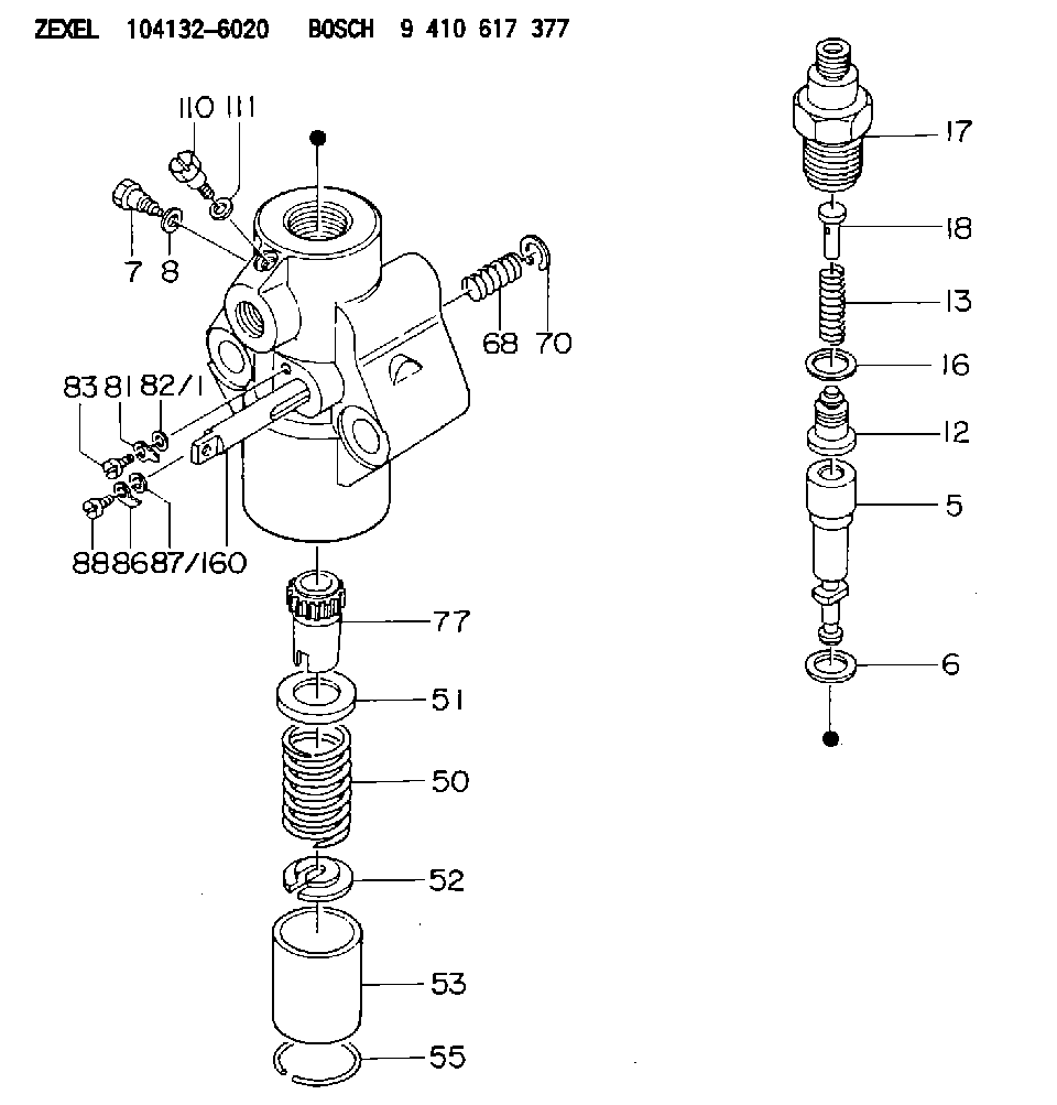
| 5. | [1] | 140153-1420 | PLUNGER-AND-BARREL ASSY |
| 6. | [1] | 029332-5040 | GASKET D30&25T0.2 |
| 7. | [1] | 140106-1400 | CAPSULE |
| 8. | [1] | 029330-8050 | GASKET |
| 12. | [1] | 140110-0520 | DELIVERY-VALVE ASSEMBLY |
| 13. | [1] | 140112-2100 | COMPRESSION SPRING |
| 16. | [1] | 140115-1600 | GASKET D30&22.5T4 |
| 17. | [1] | 140116-5600 | FITTING |
| 18. | [1] | 140117-1000 | FILLER PIECE |
| 50. | [1] | 140215-0700 | COMPRESSION SPRING |
| 51. | [1] | 140216-1100 | SLOTTED WASHER |
| 52. | [1] | 140254-1100 | SLOTTED WASHER |
| 53. | [1] | 140218-0400 | GUIDE |
| 55. | [1] | 140220-0200 | LOCKING WASHER |
| 60. | [1] | 140230-9720 | CONTROL RACK |
| 68. | [1] | 142233-0300 | COILED SPRING |
| 70. | [1] | 029601-4000 | LOCKING WASHER |
| 77. | [1] | 140241-1300 | CONTROL SLEEVE |
| 81. | [1] | 141245-2000 | POINTER |
| 82/1. | [0] | 023500-6210 | PLAIN WASHER D11&6.4T1.5 |
| 82/1. | [0] | 029300-6010 | PLAIN WASHER D11&6.4T0.8 |
| 82/1. | [0] | 029300-6020 | PLAIN WASHER D11&6.4T0.35 |
| 83. | [1] | 029050-6400 | FLAT-HEAD SCREW |
| 86. | [1] | 142249-0400 | FILLER PIECE |
| 87/1. | [0] | 023500-6210 | PLAIN WASHER D11&6.4T1.5 |
| 87/1. | [0] | 029300-6010 | PLAIN WASHER D11&6.4T0.8 |
| 87/1. | [0] | 029300-6020 | PLAIN WASHER D11&6.4T0.35 |
| 88. | [1] | 029050-6140 | FLAT-HEAD SCREW |
| 110. | [1] | 141420-0400 | BLEEDER SCREW |
| 111. | [1] | 026506-1040 | GASKET D9.9&6.2T1 |
Include in #1:
106673-7560
as _
Include in #2:
104132-6020
as INJECTION-PUMP ASSEMBLY
Cross reference number
Zexel num
Bosch num
Firm num
Name
104132-6020
9 410 617 377
EZ40045A M.BISHI-HI.-NAG
FUEL-INJECTION PUMP
* K
* K
Information:
Illustration 74 g02026337 Appendix D
Cleaned Filter Specification
Note: Scope: The following steps determine a properly cleaned Caterpillar filter.Note: This specification applies to filters that were cleaned of ash only. This specification is only valid subsequent to the "Recommended Cleaning Procedure". This specification should not be used to determine if soot filled filters are properly cleaned. All filters must be baked appropriately using the "Recommended Cleaning Procedure" prior to application of this specification.HEALTH AND SAFETY
Wear goggles, gloves, protective clothing, and a National Institute for Occupational Safety and Health (NIOSH) approved P95 or N95 half-face respirator when handling a used Diesel Particulate Filter or Catalytic Converter Muffler. Failure to do so could result in personal injury.
Adhere to all local Health and Safety rules and regulations. Use all the personal protective equipment listed below:
Respirator
Safety shoes
Safety glasses
Latex gloves
Lab coatRESOURCESNecessary equipment:
38 cm (15 inch) long by 0.9 mm (0.04 inch) thick stainless steel probe for "200 cpsi" (Cells/Square inch) filters
Tape measureMETHODEvaluation of a cleaned filter:Note: A filter MUST meet all criteria in this section below to be considered clean.
Inspect both inlet and outlet surfaces for oil/fuel contamination, gouges and/or cracks. No cracks may be visible. Gouges may not be exceed 4.0 mm (0.15 inch) deep.
There must be no filter movement within the filters banding. This movement is defined as the substrate moving past the bent-over flange. The filter must be even or below the bent-over flange.
There must not be any signs of the steel fiber ring coming loose or any mat material (cottony gauze) slipping past the filter. See Illustration 75 below.
The flanges are not damaged beyond repair.
There are no dents deeper than 6.4 mm (0.25 inch) in the outer can of the filter and the outer can is not cracked, torn or otherwise breached.
No more than 20 cells are allowed to be damaged (showing soot) on the outlet face of the filter. Refer to Illustrations 76 and 77.
Inspect the ash depth in the cells using the "Check Cell Depth" instructions below.
Illustration 75 g02026392
Proper placement of the filter within the banding
(1) Outside Can
(2) Bent-over flange
(3) Steel fiber ring
(4) Mat material
(5) FilterNote: Filter must be below the bent over-flange (2).
Illustration 76 g02026398
Acceptable filter with less than 20 damaged cells
Illustration 77 g02026399
Unacceptable filter with too many damaged cells
Check Cell Depth
Check cell depth by dropping the stainless steel probe into a cell location noted by a dot in Illustration 78 below.
Lightly tap the probe with a finger until the probe does not travel into the cell any further. Mark the probe to record the depth.
Illustration 78 g02026405
Measure the distance from the tip of the probe which entered the cell to the mark made on the probe. This distance is the cell depth. Repeat this step 17 times per Illustration 78.
If the probe travels a minimum of 28.6 cm (11.25 inch) in all cells, the filter is considered clean.
If the probe encounters heavy resistance in
Have questions with 104132-6020?
Group cross 104132-6020 ZEXEL
M.Bishi-Hi.-Nag
104132-6020
9 410 617 377
EZ40045A
FUEL-INJECTION PUMP