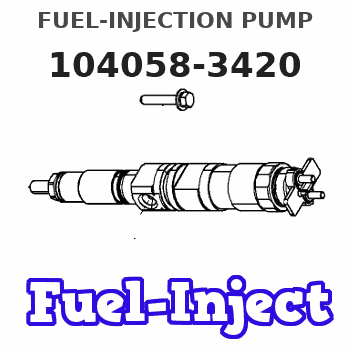
Information fuel-injection pump
BOSCH
9 410 617 552
9410617552
ZEXEL
104058-3420
1040583420
DAIHATSU
E266410040ZZ
e266410040zz

Rating:
Components :
| 0. | INJECTION-PUMP ASSEMBLY | 104058-3420 |
| 1. | _ | |
| 2. | FUEL INJECTION PUMP | |
| 3. | NUMBER PLATE | |
| 4. | _ | |
| 5. | CAPSULE | |
| 6. | ADJUSTING DEVICE | |
| 7. | NOZZLE AND HOLDER ASSY | |
| 8. | Nozzle and Holder | |
| 9. | Open Pre:MPa(Kqf/cm2) | |
| 10. | NOZZLE-HOLDER | |
| 11. | NOZZLE |
Scheme ###:
| 1. | [1] | 141052-3200 | PUMP HOUSING |
| 5. | [1] | 141175-6520 | PLUNGER-AND-BARREL ASSY |
| 7. | [1] | 141106-8100 | CAPSULE |
| 8. | [1] | 141107-0500 | GASKET |
| 12. | [1] | 141140-3320 | DELIVERY-VALVE ASSEMBLY |
| 13. | [1] | 141112-0600 | COMPRESSION SPRING |
| 16. | [1] | 141115-6100 | GASKET |
| 17. | [1] | 141136-3020 | FITTING |
| 20. | [1] | 029633-2040 | O-RING |
| 50. | [1] | 141215-2101 | COMPRESSION SPRING |
| 51. | [1] | 141216-0100 | SLOTTED WASHER |
| 52. | [1] | 141217-2800 | SLOTTED WASHER |
| 53. | [1] | 141218-4600 | PLUNGER |
| 55. | [1] | 026110-6010 | LOCKING WASHER |
| 60. | [1] | 141223-0300 | CONTROL RACK |
| 61. | [1] | 141226-3000 | BLEEDER SCREW |
| 77. | [1] | 141241-6000 | CONTROL SLEEVE |
| 81. | [1] | 141245-2000 | POINTER |
| 82/1. | [0] | 023500-6210 | PLAIN WASHER D11&6.4T1.5 |
| 82/1. | [0] | 029300-6010 | PLAIN WASHER D11&6.4T0.8 |
| 82/1. | [0] | 029300-6020 | PLAIN WASHER D11&6.4T0.35 |
| 83. | [1] | 020006-1440 | BLEEDER SCREW M6P1L14 |
| 93. | [1] | 029732-2050 | EYE BOLT |
| 94. | [2] | 141403-0500 | GASKET |
| 94. | [2] | 141403-0500 | GASKET |
| 110. | [1] | 140420-1600 | BLEEDER SCREW |
| 111. | [1] | 141421-0000 | GASKET |
Include in #2:
104058-3420
as INJECTION-PUMP ASSEMBLY
Cross reference number
Zexel num
Bosch num
Firm num
Name
Information:
Do not operate or work on this product unless you have read and understood the instruction and warnings in the relevant Operation and Maintenance Manuals and relevant service literature. Failure to follow the instructions or heed the warnings could result in injury or death. Proper care is your responsibility.
There have been instances of the following diagnostic codes becoming active:
Table 1
J1939 Code CDL Code Code Description
1184-3 3782-3 Engine Turbocharger #1 Turbine Outlet Temperature : Voltage Above Normal
1184-4 3782-4 Engine Turbocharger #1 Turbine Outlet Temperature : Voltage Below Normal
3242-3 2452-3 DPF #1 Intake Temperature Sensor : Voltage Above Normal
3242-4 2452-4 DPF #1 Intake Temperature Sensor : Voltage Below Normal
4360-3 3105-3 Aftertreatment #1 SCR Catalyst Intake Gas Temperature Sensor : Voltage Above Normal
4360-4 3105-4 Aftertreatment #1 SCR Catalyst Intake Gas Temperature Sensor : Voltage Below Normal One root cause of the diagnostic codes has been identified as electrical noise overwriting data on the memory chip of the DPF/SCR intake temperature sensor. Improved sensor firmware has resolved this issue.A fault could not be found with some of the returned parts. A new troubleshooting procedure has been released. Refer to Troubleshooting, Sensor Signal (PWM) - Test.
