Information fuel-injection pump
BOSCH
9 410 617 988
9410617988
ZEXEL
104058-3370
1040583370
Rating:
Components :
| 0. | INJECTION-PUMP ASSEMBLY | 104058-3370 |
| 1. | _ | |
| 2. | FUEL INJECTION PUMP | |
| 3. | NUMBER PLATE | |
| 4. | _ | |
| 5. | CAPSULE | |
| 6. | ADJUSTING DEVICE | |
| 7. | NOZZLE AND HOLDER ASSY | |
| 8. | Nozzle and Holder | |
| 9. | Open Pre:MPa(Kqf/cm2) | |
| 10. | NOZZLE-HOLDER | |
| 11. | NOZZLE |
Scheme ###:
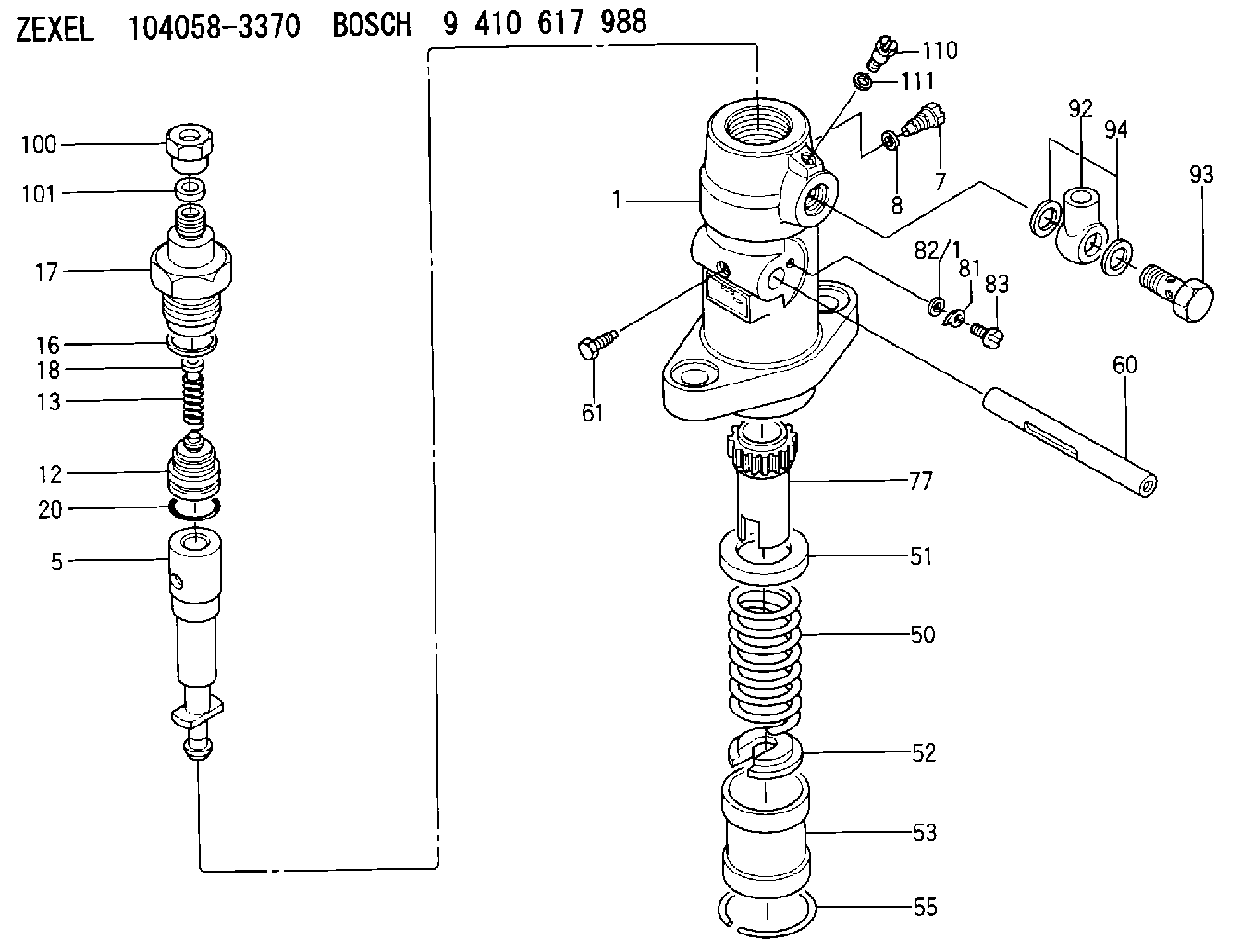
| 1. | [1] | 141050-5800 | PUMP HOUSING |
| 5. | [1] | 141170-9220 | PLUNGER-AND-BARREL ASSY |
| 5/1. | [1] | 141165-3000 | CYLINDER |
| 5/2. | [1] | 141170-9200 | PLUNGER |
| 7. | [1] | 141106-7500 | CAPSULE |
| 8. | [1] | 029331-0020 | GASKET |
| 12. | [1] | 141140-0420 | DELIVERY-VALVE ASSEMBLY |
| 12/1. | [1] | 141140-0400 | VALVE BODY |
| 12/2. | [1] | 141111-3100 | SEAT;D.V. |
| 13. | [1] | 141112-0600 | COMPRESSION SPRING |
| 16. | [1] | 141115-4400 | GASKET |
| 17. | [1] | 141126-1000 | FITTING |
| 18. | [1] | 141117-3400 | SLOTTED WASHER |
| 20. | [1] | 029633-2040 | O-RING |
| 50. | [1] | 141215-4001 | COMPRESSION SPRING |
| 51. | [1] | 141216-0100 | SLOTTED WASHER |
| 52. | [1] | 141217-2800 | SLOTTED WASHER |
| 53. | [1] | 141218-4600 | PLUNGER |
| 55. | [1] | 026110-6010 | LOCKING WASHER |
| 60. | [1] | 141243-5200 | CONTROL RACK |
| 61. | [1] | 141226-3000 | BLEEDER SCREW |
| 77. | [1] | 141241-0300 | CONTROL SLEEVE |
| 81. | [1] | 141245-2000 | POINTER |
| 82/1. | [0] | 023500-6210 | PLAIN WASHER D11&6.4T1.5 |
| 82/1. | [0] | 029300-6010 | PLAIN WASHER D11&6.4T0.8 |
| 82/1. | [0] | 029300-6020 | PLAIN WASHER D11&6.4T0.35 |
| 83. | [1] | 020006-1440 | BLEEDER SCREW M6P1L14 |
| 92. | [1] | 029702-2020 | INLET UNION |
| 93. | [1] | 029732-2050 | EYE BOLT |
| 94. | [2] | 026522-2740 | GASKET D26.9&22.2T1 |
| 100. | [1] | 029761-8190 | UNION NUT |
| 101. | [1] | 029351-0030 | PLAIN WASHER |
| 110. | [1] | 140420-1600 | BLEEDER SCREW |
| 111. | [1] | 026506-1040 | GASKET D9.9&6.2T1 |
Include in #1:
107691-2710
as _
Include in #2:
104058-3370
as INJECTION-PUMP ASSEMBLY
Cross reference number
Zexel num
Bosch num
Firm num
Name
104058-3370
9 410 617 988
FUEL-INJECTION PUMP
K 24EA PF-1W(M) PF
K 24EA PF-1W(M) PF
Information:
Parts Location
Illustration 2 g01631813
(A) Flywheel (B) Fender Group (C) Tank Group (1) 319-8929 Diesel Particulate Filter Gp (2) 329-1696 Tube (3) 329-1701 Tube As (4) 295-3044 Exhaust Support Gp (5) 8T-4223 Hard Washer (6) 8T-4183 Bolt (7) 270-0112 Bellows (8) 7E-3870 Muffler Clamp (9) 247-5011 Pipe Clamp (10) 9Y-8315 Pipe Clamp (11) 8S-5120 Extension Pipe (12) 7S-4994 Rain Cap As (13) 241-6170 Plug (14) 8T-6765 Pipe Plug Installation Procedure
Diesel Particulate Filter Installation
Illustration 3 g01630053
(4) 295-3044 Exhaust Support Gp (Lower half) (5) 8T-4223 Hard Washer (6) 8T-4183 Bolt
Install the lower half of each new 295-3044 Exhaust Support Gp (4) on top of the hood, towards the right side of the cab, by using four new 8T-4183 Bolts (6), and four new 8T-4223 Hard Washers (5). Refer to Illustration 3.
Illustration 4 g01630056
(1) 319-8929 Diesel Particulate Filter Gp
Install the new 319-8929 Diesel Particulate Filter Gp (1) onto the lower half of exhaust support group (4). Refer to Illustration 4.
Illustration 5 g01630074
(4a) Upper half (Exhaust support group) (4b) Bolt (4c) Hard washer (4d) Weld nut
Install the upper half (4a) of exhaust support group by using two bolts (4b), two hard washers (4c), and two weld nuts (4d). Repeat for the other exhaust support group. Refer to Illustration 5.
Illustration 6 g01630094
(2) 329-1696 Tube (3) 329-1701 Tube As (7) 270-0112 Bellows (8) 7E-3870 Muffler Clamp
Install the new 329-1696 Tube (2) to the inlet module tube of the diesel particulate filter group by using one new 7E-3870 Muffler Clamp (8). Refer to Illustration 6.
Install the new 270-0112 Bellows (7) to tube (2) by using one new 7E-3870 Muffler Clamp (8). Refer to Illustration 6.
Install the new 329-1701 Tube Assembly (3) to bellows (7) by using one new 7E-3870 Muffler Clamp (8). Refer to Illustration 6.
Illustration 7 g01630133
(9) 247-5011 Pipe Clamp (11) 8S-5120 Extension Pipe
Install 8S-5120 Extension Pipe (11) to the outlet module tube of the diesel particulate filter group by using a new 247-5011 Pipe Clamp (9). Refer to Illustration 7.
Illustration 8 g01630173
(12) 7S-4994 Rain Cap As
Install the new 7S-4994 Rain Cap Assembly (12) on extension pipe (11). Refer to Illustration 8.
Illustration 9 g01630234
(13) 241-6170 Plug (14) 8T-6765 Pipe Plug
Install a new 241-6170 Plug (13) and a new 8T-6765 Pipe Plug (14) on tube assembly (3) at the respective slots provided. Refer to Illustration 9.
Reconnect the drain lines.Exhaust Monitor Installation
Refer to Special Instruction, REHS5606, "Installation and Operation of the Caterpillar Diesel Particulate Filter (DPF) and the Diagnostic Module for Non-Road Machine Applications (Non-California Applications)" for information regarding the installation and the operation of the exhaust monitor.The exhaust monitor is a device designed to monitor the Caterpillar DPF system continuously. The exhaust monitor provides critical information to the vehicle operator and maintenance
Have questions with 104058-3370?
Group cross 104058-3370 ZEXEL
Fuji-Diesel
Daihatsu
Fuji-Diesel
104058-3370
9 410 617 988
FUEL-INJECTION PUMP