Information fuel-injection pump
BOSCH
9 410 617 015
9410617015
ZEXEL
104057-3210
1040573210
NIIGATA-URAWA
73047012A
73047012a
Rating:
Components :
| 0. | INJECTION-PUMP ASSEMBLY | 104057-3210 |
| 1. | _ | |
| 2. | FUEL INJECTION PUMP | |
| 3. | NUMBER PLATE | |
| 4. | _ | |
| 5. | CAPSULE | |
| 6. | ADJUSTING DEVICE | |
| 7. | NOZZLE AND HOLDER ASSY | |
| 8. | Nozzle and Holder | |
| 9. | Open Pre:MPa(Kqf/cm2) | |
| 10. | NOZZLE-HOLDER | |
| 11. | NOZZLE | 105011-7310 |
Scheme ###:
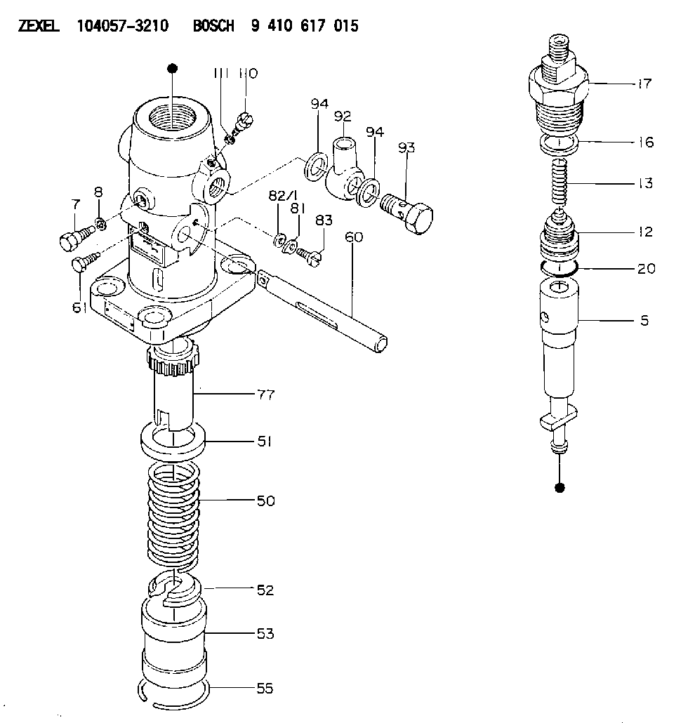
| 5. | [1] | 141170-6920 | PLUNGER-AND-BARREL ASSY |
| 7. | [1] | 141106-8200 | CAPSULE |
| 8. | [1] | 029341-0010 | GASKET |
| 12. | [1] | 141110-8020 | DELIVERY-VALVE ASSEMBLY |
| 13. | [1] | 141112-0600 | COMPRESSION SPRING |
| 16. | [1] | 141115-4400 | GASKET |
| 17. | [1] | 141126-9420 | FITTING |
| 20. | [1] | 029633-2040 | O-RING |
| 50. | [1] | 141215-0300 | COMPRESSION SPRING |
| 51. | [1] | 141216-0100 | SLOTTED WASHER |
| 52. | [1] | 141217-2700 | SLOTTED WASHER |
| 53. | [1] | 141218-4600 | PLUNGER |
| 55. | [1] | 026110-6010 | LOCKING WASHER |
| 60. | [1] | 141243-0800 | CONTROL RACK |
| 61. | [1] | 141226-3000 | BLEEDER SCREW |
| 77. | [1] | 141241-0200 | CONTROL SLEEVE |
| 81. | [1] | 141245-2000 | POINTER |
| 82/1. | [0] | 023500-6210 | PLAIN WASHER D11&6.4T1.5 |
| 82/1. | [0] | 029300-6010 | PLAIN WASHER D11&6.4T0.8 |
| 82/1. | [0] | 029300-6020 | PLAIN WASHER D11&6.4T0.35 |
| 83. | [1] | 020006-1440 | BLEEDER SCREW M6P1L14 |
| 92. | [1] | 029702-2020 | INLET UNION |
| 93. | [1] | 029732-2050 | EYE BOLT |
| 94. | [2] | 026522-2740 | GASKET D26.9&22.2T1 |
| 94. | [2] | 026522-2740 | GASKET D26.9&22.2T1 |
| 110. | [1] | 140420-1600 | BLEEDER SCREW |
| 111. | [1] | 026506-1040 | GASKET D9.9&6.2T1 |
Include in #1:
106876-2000
as _
Include in #2:
104057-3210
as INJECTION-PUMP ASSEMBLY
Cross reference number
Zexel num
Bosch num
Firm num
Name
9 410 617 015
73047012A NIIGATA-URAWA
FUEL-INJECTION PUMP
* K 24EA PF-1W(M) PF
* K 24EA PF-1W(M) PF
9 410 617 015
73047012C NIIGATA-TEKKOU
FUEL-INJECTION PUMP
* K 24EA PF-1W(M) PF
* K 24EA PF-1W(M) PF
Information:
Introduction
Do not perform any procedure in this Special Instruction until you have read the information and you understand the information.DEF injectors are being replaced in the field and returned to Caterpillar for testing. Results of the testing are finding a large portion of the returned DEF injectors are found to be fault not repeated.This form is to be used and filled out in any case that a DEF injector is being replaced.The DEF injector troubleshooting return form needs to be completed and included within failed part returns documenting what was found that led to DEF injector replacement. Attach the photos of DEF injector tip and mount area along with a Product Status Report to the SIMS claim.References
Table 1
Engine Publication Type Media Number
C7.1 Troubleshooting UENR0668
Testing and Adjusting UENR4467
Disassembly and Assembly UENR4468
C9.3 Troubleshooting UENR0978
Testing and Adjusting UENR3402
Disassembly and Assembly UENR0130
C13 Troubleshooting UENR0955
Testing and Adjusting UENR4302
Disassembly and Assembly UENR0131
C15/C18 Troubleshooting UENR0955
Testing and Adjusting UENR3351
Disassembly and Assembly UENR0132 Procedure
What code are you troubleshooting? __________
Follow the correct troubleshooting procedure. Reference Table 1 for correct media number to use.
When troubleshooting procedure requests the DEF quality check, DEF injector resistance measurement, or Dosing Accuracy Test, document those results in Tables 2, 3, and 4.Tables
Table 2
DEF Quality Results
Step Instruction Completed (Yes/No) Result Comments Units
1 Follow the Testing and Adjusting procedure for "Diesel Exhaust Fluid Quality - Test"
2 DEF Contamination Test Pass / Fail
3 DEF Concentration Test % at 20° C (68° F)
Illustration 1 g06175415
Table 3
Injector Resistance Measurement
Step Instruction Completed (Yes/No) Result Comments Units
1 Turn the keyswitch to the OFF position. Allow 2 minutes to elapse before proceeding.
2 Disconnect the DEF injectors from the applicable harness.
3 Inspect the connector for damage and debris.
4 Measure the temperature of the injector (aluminum body). C
5 Connect two 398-4987 Probes to the DEF injector. The connectors must be used to prevent damage to the DEF injector connector. Reference Illustration 1 for example.
6 Measure the resistance of the DEF injector. Ohms
Table 4
Dosing Accuracy Test
Step Instruction Completed (Yes/No) Result Comments Units
1 Follow the Testing and Adjusting procedure for "Aftertreatment SCR System Dosing - Test"
2 Remove the injector from the DPF outlet.
3 Take a photograph of the DEF injector mount on the DPF outlet and the tip of the DEF injector.
4 Install the injector on the beaker.
5 Run the DEF System Dosing Accuracy test through Cat® Electronic Technician (ET).
6 Use the beaker to measure the amount of fluid from the dosing test. ml
7 Repeat the test to verify consistency. ml
8 Install the injector back onto the DPF outlet.