Information fuel-injection pump
BOSCH
9 410 617 542
9410617542
ZEXEL
104036-6060
1040366060
Rating:
Components :
| 0. | INJECTION-PUMP ASSEMBLY | 104036-6060 |
| 1. | _ | |
| 2. | FUEL INJECTION PUMP | |
| 3. | NUMBER PLATE | |
| 4. | _ | |
| 5. | CAPSULE | |
| 6. | ADJUSTING DEVICE | |
| 7. | NOZZLE AND HOLDER ASSY | |
| 8. | Nozzle and Holder | |
| 9. | Open Pre:MPa(Kqf/cm2) | |
| 10. | NOZZLE-HOLDER | 105033-4150 |
| 11. | NOZZLE | 105011-0790 |
Scheme ###:
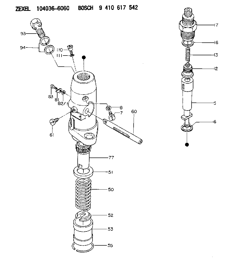
| 5. | [1] | 133101-0620 | PLUNGER-AND-BARREL ASSY |
| 6. | [1] | 029332-1010 | GASKET |
| 7. | [1] | 141106-7900 | CAPSULE |
| 8. | [1] | 029330-8050 | GASKET |
| 12. | [1] | 140110-0120 | DELIVERY-VALVE ASSEMBLY |
| 13. | [1] | 140112-1900 | COMPRESSION SPRING |
| 16. | [1] | 140115-1100 | GASKET |
| 17. | [1] | 140116-5200 | FITTING |
| 50. | [1] | 140215-1400 | COMPRESSION SPRING |
| 51. | [1] | 140216-1100 | SLOTTED WASHER |
| 52. | [1] | 140254-1100 | SLOTTED WASHER |
| 53. | [1] | 140218-0400 | GUIDE |
| 55. | [1] | 140220-0200 | LOCKING WASHER |
| 60. | [1] | 140223-5400 | CONTROL RACK |
| 61. | [1] | 141226-3000 | BLEEDER SCREW |
| 77. | [1] | 140241-1100 | CONTROL SLEEVE |
| 81. | [1] | 141245-2000 | POINTER |
| 82/1. | [0] | 023500-6210 | PLAIN WASHER D11&6.4T1.5 |
| 82/1. | [0] | 029300-6010 | PLAIN WASHER D11&6.4T0.8 |
| 82/1. | [0] | 029300-6020 | PLAIN WASHER D11&6.4T0.35 |
| 83. | [1] | 020006-1440 | BLEEDER SCREW M6P1L14 |
| 93. | [1] | 029731-8070 | EYE BOLT |
| 94. | [2] | 026518-2240 | GASKET D21.9&18.2T1 |
| 110. | [1] | 140420-1600 | BLEEDER SCREW |
| 111. | [1] | 026506-1040 | GASKET D9.9&6.2T1 |
Include in #2:
104036-6060
as INJECTION-PUMP ASSEMBLY
Cross reference number
Zexel num
Bosch num
Firm num
Name
Information:
Image1.1.1
3) Remove the sensor box bracket and heat shield from the sensor box. Keep the bolt hardware for re-use.
Image1.2.1
4) Install new sensor box bracket and existing heat shield. Tighten all 6 bolts to a torque of 12 +/- 3 Nm (106 +/- 27 lb-in).
Image1.3.1
5) Where applicable perform the DPF sensor line update, Service Letter REBE3397 at this step.
6) Install sensor box, pressure lines, and thermocouples onto DPF.
Reference appropriate Disassembly and Assembly manual for proper torque and use of anti-seize.
Image1.4.1
7) Start the engine and use CAT ET to ensure that the status parameter Diesel Particulate Trap #1 Differential Pressure has a value greater than zero. Also ensure status parameters Diesel Particulate Trap #1 Intake Temperature, and Diesel Particulate Trap #1 Outlet Temperature show reasonable values and increase with the rising exhaust temperatures.