Information fuel-injection pump
BOSCH
9 410 613 123
9410613123
ZEXEL
103088-9210
1030889210

Rating:
Scheme ###:
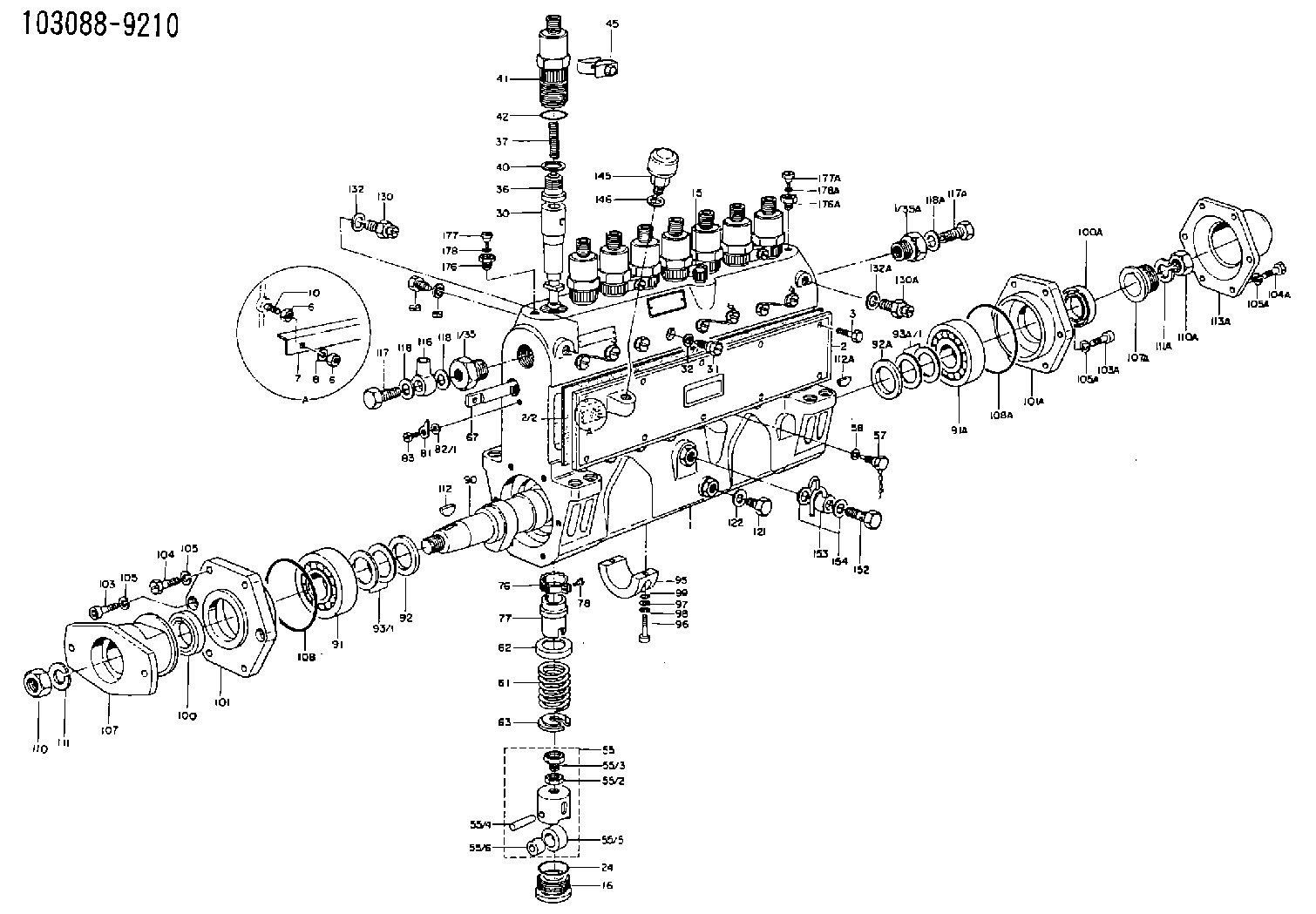
| 1. | [1] | 133050-5020 | PUMP HOUSING |
| 1/35. | [1] | 132400-0900 | ADAPTOR |
| 1/35A. | [1] | 132400-1000 | ADAPTOR |
| 2. | [1] | 133010-6220 | COVER |
| 2/2. | [1] | 133011-1300 | GASKET |
| 3. | [10] | 020106-1240 | BLEEDER SCREW M6P1.0L12 |
| 6. | [4] | 013020-6020 | UNION NUT M6P1H5 |
| 6. | [4] | 013020-6020 | UNION NUT M6P1H5 |
| 7. | [1] | 133021-0500 | COVER |
| 8. | [2] | 014110-6410 | LOCKING WASHER |
| 10. | [2] | 139006-0300 | STUD |
| 15. | [1] | 133030-1620 | LEVEL INDICATOR |
| 16. | [8] | 133034-0100 | CAPSULE |
| 23. | [1] | 133041-0400 | GASKET |
| 24. | [8] | 029633-4010 | O-RING |
| 30. | [8] | 133151-4020 | PLUNGER-AND-BARREL ASSY |
| 31. | [8] | 133106-0500 | CAPSULE |
| 32. | [8] | 026510-1440 | GASKET D13.9&10.2T1 |
| 36. | [8] | 133110-1320 | DELIVERY-VALVE ASSEMBLY |
| 37. | [8] | 133112-0100 | COMPRESSION SPRING |
| 40. | [8] | 133115-1000 | GASKET |
| 41. | [8] | 133116-2900 | FITTING |
| 42. | [8] | 029632-5030 | O-RING |
| 45. | [4] | 133122-1520 | PLATE |
| 55. | [8] | 133200-1120 | TAPPET |
| 55/2. | [1] | 133201-0101 | UNION NUT |
| 55/3. | [1] | 133202-0100 | HEXAGON SCREW |
| 55/4. | [1] | 133203-0400 | BEARING PIN |
| 55/5. | [1] | 133204-0300 | ROLLER |
| 55/6. | [1] | 133205-0300 | BUSHING |
| 57. | [8] | 133210-0300 | FLAT-HEAD SCREW |
| 58. | [8] | 026510-1340 | GASKET D13.4&10.2T1 |
| 61. | [8] | 133215-0100 | COMPRESSION SPRING |
| 62. | [8] | 133216-0100 | SLOTTED WASHER |
| 63. | [8] | 133217-0100 | SLOTTED WASHER |
| 67. | [1] | 133258-0600 | CONTROL RACK |
| 68. | [1] | 133226-0600 | FLAT-HEAD SCREW |
| 69. | [1] | 023700-8120 | TAB WASHER |
| 76. | [8] | 133240-0100 | PINION |
| 77. | [8] | 133241-0200 | CONTROL SLEEVE |
| 78. | [8] | 131242-0100 | FLAT-HEAD SCREW |
| 81. | [1] | 133245-0300 | POINTER |
| 82/1. | [0] | 029300-5020 | PLAIN WASHER D10&5.1T1.5 |
| 82/1. | [0] | 029310-5080 | SHIM D10&5T0.2 |
| 82/1. | [0] | 029310-5090 | SHIM D10&5.1T0.5 |
| 82/1. | [0] | 029310-5110 | SHIM D10&5.1T1 |
| 83. | [1] | 021305-0940 | FLAT-HEAD SCREW |
| 90. | [1] | 133381-0601 | CAMSHAFT |
| 91. | [1] | 016603-3230 | BEARING PLATE |
| 91A. | [1] | 016603-3230 | BEARING PLATE |
| 92. | [1] | 133302-0200 | SPACER RING |
| 92A. | [1] | 133302-0200 | SPACER RING |
| 93/1. | [0] | 029313-0010 | SHIM D45&30.2T0.1 |
| 93/1. | [0] | 029313-0020 | SHIM D45&30.2T0.12 |
| 93/1. | [0] | 029313-0030 | SHIM D45&30.2T0.14 |
| 93/1. | [0] | 029313-0040 | SHIM D45&30.2T0.16 |
| 93/1. | [0] | 029313-0050 | SHIM D45&30.2T0.18 |
| 93/1. | [0] | 029313-0060 | SHIM D45&30.2T0.5 |
| 93/1. | [0] | 029313-0070 | SHIM D45&30.2T1 |
| 93A/1. | [0] | 029313-0010 | SHIM D45&30.2T0.1 |
| 93A/1. | [0] | 029313-0020 | SHIM D45&30.2T0.12 |
| 93A/1. | [0] | 029313-0030 | SHIM D45&30.2T0.14 |
| 93A/1. | [0] | 029313-0040 | SHIM D45&30.2T0.16 |
| 93A/1. | [0] | 029313-0050 | SHIM D45&30.2T0.18 |
| 93A/1. | [0] | 029313-0060 | SHIM D45&30.2T0.5 |
| 93A/1. | [0] | 029313-0070 | SHIM D45&30.2T1 |
| 95. | [1] | 133306-0200 | BEARING SHELL |
| 96. | [2] | 010208-4040 | HEX-SOCKET-HEAD CAP SCREW |
| 97. | [2] | 023500-8120 | PLAIN WASHER |
| 98. | [2] | 014110-8410 | LOCKING WASHER |
| 99. | [2] | 029630-9020 | O-RING |
| 100. | [1] | 029623-0010 | PACKING RING |
| 100A. | [1] | 029623-0010 | PACKING RING |
| 101. | [1] | 133316-3900 | COVER |
| 101A. | [1] | 133316-3900 | COVER |
| 103. | [2] | 010208-2020 | HEX-SOCKET-HEAD CAP SCREW |
| 103A. | [2] | 010208-2020 | HEX-SOCKET-HEAD CAP SCREW |
| 104. | [4] | 029010-8010 | BLEEDER SCREW |
| 104A. | [4] | 020308-3640 | BLEEDER SCREW M8P1.25L36 |
| 105. | [6] | 014110-8410 | LOCKING WASHER |
| 105. | [6] | 014110-8410 | LOCKING WASHER |
| 105A. | [6] | 014110-8410 | LOCKING WASHER |
| 105A. | [6] | 014110-8410 | LOCKING WASHER |
| 107. | [1] | 156611-6500 | COUPLING PLATE |
| 107A. | [1] | 133323-0600 | BUSHING |
| 108. | [1] | 029637-6010 | O-RING |
| 108A. | [1] | 029637-6010 | O-RING |
| 110. | [1] | 023012-0040 | UNION NUT M20P1.5H16 |
| 110A. | [1] | 023012-0040 | UNION NUT M20P1.5H16 |
| 111. | [1] | 014112-0410 | LOCKING WASHER |
| 111A. | [1] | 014112-0410 | LOCKING WASHER |
| 112. | [1] | 025806-2210 | WOODRUFF KEY |
| 112A. | [1] | 025806-2210 | WOODRUFF KEY |
| 113A. | [1] | 133328-1800 | CAP |
| 116. | [1] | 029701-8180 | INLET UNION |
| 117. | [1] | 029731-8250 | EYE BOLT |
| 117A. | [1] | 029111-4110 | CAPSULE |
| 118. | [2] | 026518-2240 | GASKET D21.9&18.2T1 |
| 118. | [2] | 026518-2240 | GASKET D21.9&18.2T1 |
| 118A. | [1] | 026514-1840 | GASKET D17.9&14.2T1 |
| 121. | [1] | 133486-0200 | CAPSULE |
| 122. | [1] | 026510-1340 | GASKET D13.4&10.2T1 |
| 130. | [1] | 131420-0720 | BLEEDER SCREW |
| 130A. | [1] | 131420-0720 | BLEEDER SCREW |
| 132. | [1] | 026512-1540 | GASKET D15.4&12.2T1.50 |
| 132A. | [1] | 026512-1540 | GASKET D15.4&12.2T1.50 |
| 145. | [1] | 155406-0220 | AIR FILTER |
| 146. | [1] | 026512-1540 | GASKET D15.4&12.2T1.50 |
| 152. | [1] | 131601-4300 | EYE BOLT |
| 153. | [1] | 131431-5520 | PIPE |
| 154. | [2] | 026510-1340 | GASKET D13.4&10.2T1 |
| 176. | [1] | 131419-0200 | ADAPTOR |
| 176A. | [1] | 131419-0200 | ADAPTOR |
| 177. | [1] | 131420-0200 | BLEEDER SCREW |
| 177A. | [1] | 131420-0200 | BLEEDER SCREW |
| 178. | [1] | 026506-1040 | GASKET D9.9&6.2T1 |
| 178A. | [1] | 026506-1040 | GASKET D9.9&6.2T1 |
Cross reference number
Zexel num
Bosch num
Firm num
Name
103088-9210
9 410 613 123
FUEL-INJECTION PUMP
* Q
* Q
Information:
a) Remove by screwing flywheel attaching bolts uniformly into the bolt holes for removal. Pull out using the special tool, Gear Puller. Do not remove the gear by striking it. b) Heat the gear to about 100°C by a heater, etc. Aligning the crankshaft dowel pin with the dowel pin hole in the gear, insert the shaft into the gear, lightly striking the gear end face with a soft hammer.c) Install the sleeve using the special tool, Oil Seal and Sleeve Installer. [Refer to Item (2) - (b), Section 5.1.3.](3) Reassembly Reassembly
(a) Installation of oil jet (excluding 6D14, 6D15) Fix the oil jet aligning with the locating pin and tighten the check valve to specified torque. Bend lock washer onto the check valve to prevent it from turning.(b) Installation of thrust plate and main bearing 1. Install the thrust plate with its side having no oil groove toward the crankcase.2. Line up the lug of main bearing with the lug groove in crankcase. Note that the upper main bearing has an oil hole, which must not be confused with the lower bearing.3. Apply engine oil to all sliding surfaces.(c) Installation of main bearing cap 1) Fit the lower main bearing into the main bearing cap. At the time, make sure that the main bearing lug is aligned with the main bearing cap lug groove.2) Install also the thrust plate onto the main bearing cap in the rear-end position.3) Make sure that the main bearing cap lug groove and crankcase lug groove are on the same side. 1. Face the side of thrust plate having no oil groove toward the rear end of the crankcase and toward the main bearing cap.2. Use thrust plates of the same size for the rear end of the crankcase and main bearing cap rear end. 4) Tighten the main bearing cap bolt to specification. Then, make sure that the crankshaft turns smoothly by hand.5) Measure the crankshaft end play to determine if it is within the nominal value [Refer to Item (1) - (c), Section 5.1.4.].(d) Reassembly of piston and connecting rod 1) Assemble the piston and the connecting rod, ensuring correct direction as illustrated.2) Insert the piston pin to couple the piston and connecting rod. Mount the snap ring to hold the piston pin in position. The piston pin is a clearance fit in the piston. If the piston pin is hard to fit, heat the piston with a piston heater or hot water. 1. Keep the piston weight difference for one engine within 10 g.2. Use connecting rod assembly of same weight mark for an engine.3. Check to see that the size mark of the piston is same as that of the cylinder liner.4. Apply engine oil to sliding surfaces. 3) The connecting rod bolts do not normally need removal; however, where replacement is necessary for damaged bolt, install new bolts by using the following procedures. Make sure that the connecting rod bolt hole is free from damage and burrs. Then,
(a) Installation of oil jet (excluding 6D14, 6D15) Fix the oil jet aligning with the locating pin and tighten the check valve to specified torque. Bend lock washer onto the check valve to prevent it from turning.(b) Installation of thrust plate and main bearing 1. Install the thrust plate with its side having no oil groove toward the crankcase.2. Line up the lug of main bearing with the lug groove in crankcase. Note that the upper main bearing has an oil hole, which must not be confused with the lower bearing.3. Apply engine oil to all sliding surfaces.(c) Installation of main bearing cap 1) Fit the lower main bearing into the main bearing cap. At the time, make sure that the main bearing lug is aligned with the main bearing cap lug groove.2) Install also the thrust plate onto the main bearing cap in the rear-end position.3) Make sure that the main bearing cap lug groove and crankcase lug groove are on the same side. 1. Face the side of thrust plate having no oil groove toward the rear end of the crankcase and toward the main bearing cap.2. Use thrust plates of the same size for the rear end of the crankcase and main bearing cap rear end. 4) Tighten the main bearing cap bolt to specification. Then, make sure that the crankshaft turns smoothly by hand.5) Measure the crankshaft end play to determine if it is within the nominal value [Refer to Item (1) - (c), Section 5.1.4.].(d) Reassembly of piston and connecting rod 1) Assemble the piston and the connecting rod, ensuring correct direction as illustrated.2) Insert the piston pin to couple the piston and connecting rod. Mount the snap ring to hold the piston pin in position. The piston pin is a clearance fit in the piston. If the piston pin is hard to fit, heat the piston with a piston heater or hot water. 1. Keep the piston weight difference for one engine within 10 g.2. Use connecting rod assembly of same weight mark for an engine.3. Check to see that the size mark of the piston is same as that of the cylinder liner.4. Apply engine oil to sliding surfaces. 3) The connecting rod bolts do not normally need removal; however, where replacement is necessary for damaged bolt, install new bolts by using the following procedures. Make sure that the connecting rod bolt hole is free from damage and burrs. Then,
Have questions with 103088-9210?
Group cross 103088-9210 ZEXEL
103088-9210
9 410 613 123
FUEL-INJECTION PUMP