Information fuel-injection pump
BOSCH
9 410 611 316
9410611316
ZEXEL
103086-9140
1030869140
Rating:
Scheme ###:
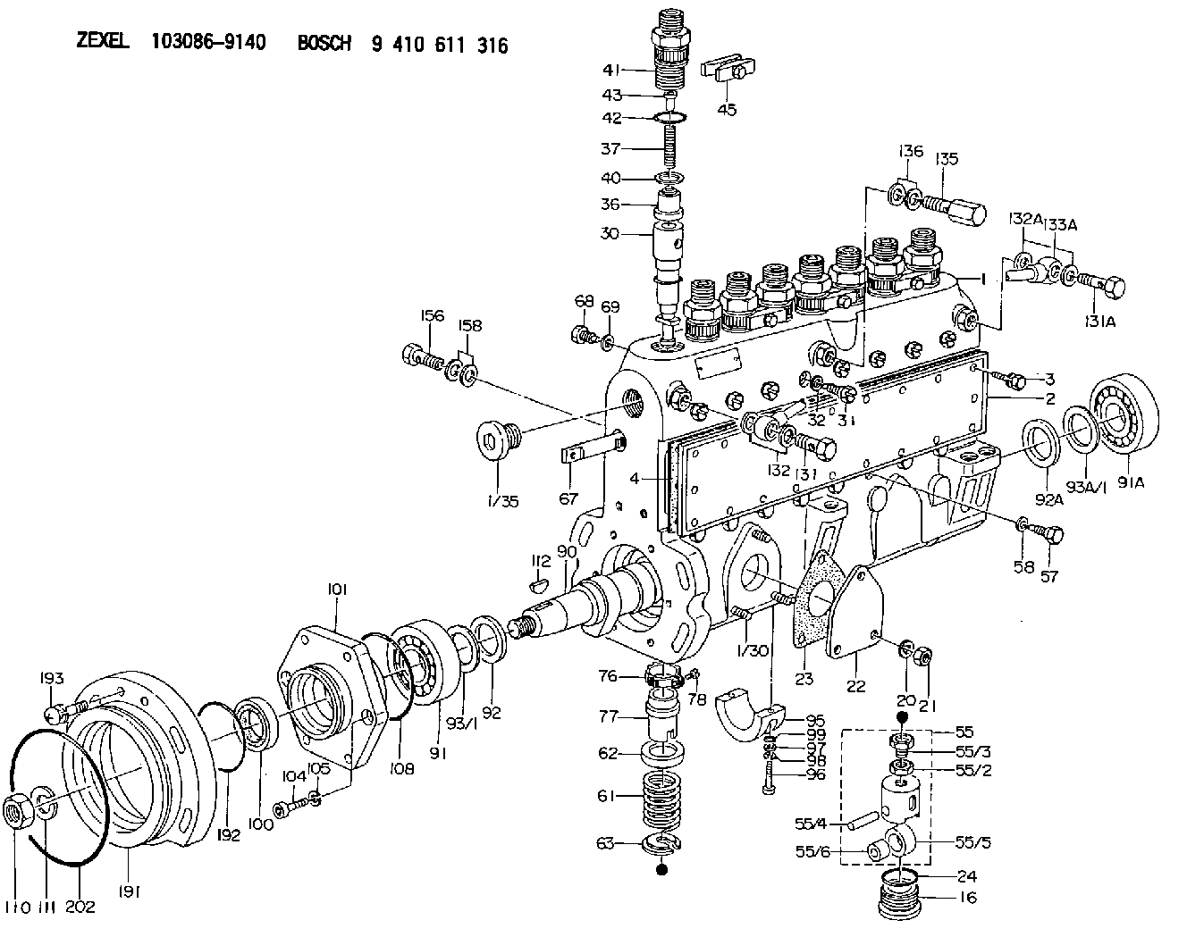
| 1. | [1] | 133051-4221 | PUMP HOUSING |
| 1/30. | [3] | 029040-6020 | STUD |
| 1/35. | [1] | 029112-4010 | CAPSULE |
| 2. | [1] | 133010-7500 | COVER |
| 3. | [20] | 020106-1440 | BLEEDER SCREW M6P1.0L14 |
| 4. | [1] | 133011-1900 | GASKET |
| 16. | [8] | 133034-0100 | CAPSULE |
| 20. | [3] | 014110-6410 | LOCKING WASHER |
| 21. | [3] | 013020-6040 | UNION NUT M6P1H5 |
| 22. | [1] | 133040-0100 | COVER |
| 23. | [1] | 133041-0400 | GASKET |
| 24. | [8] | 029633-4010 | O-RING |
| 30. | [8] | 133151-7420 | PLUNGER-AND-BARREL ASSY |
| 31. | [8] | 133106-0800 | CAPSULE |
| 32. | [8] | 026510-1440 | GASKET D13.9&10.2T1 |
| 36. | [8] | 133110-3120 | DELIVERY-VALVE ASSEMBLY |
| 37. | [8] | 133112-0700 | COILED SPRING |
| 40. | [8] | 133115-1500 | GASKET |
| 41. | [8] | 133116-3520 | FITTING |
| 42. | [8] | 029632-5030 | O-RING |
| 43. | [8] | 134117-0500 | FILLER PIECE |
| 45. | [4] | 133122-1420 | PLATE |
| 55. | [8] | 133200-1920 | TAPPET |
| 55/2. | [1] | 133201-0300 | UNION NUT |
| 55/3. | [1] | 133202-0400 | HEXAGON SCREW |
| 55/4. | [1] | 133203-0400 | BEARING PIN |
| 55/5. | [1] | 133204-0600 | ROLLER |
| 55/6. | [1] | 133205-0300 | BUSHING |
| 57. | [8] | 133210-0400 | FLAT-HEAD SCREW |
| 58. | [8] | 026510-1340 | GASKET D13.4&10.2T1 |
| 61. | [8] | 133215-0900 | COMPRESSION SPRING |
| 62. | [8] | 133216-0200 | SLOTTED WASHER |
| 63. | [8] | 133217-0100 | SLOTTED WASHER |
| 67. | [1] | 133258-1900 | CONTROL RACK |
| 68. | [1] | 133226-0700 | FLAT-HEAD SCREW |
| 69. | [1] | 133516-0400 | TAB WASHER |
| 76. | [8] | 133240-0100 | PINION |
| 77. | [8] | 133241-0200 | CONTROL SLEEVE |
| 78. | [8] | 131242-0100 | FLAT-HEAD SCREW |
| 90. | [1] | 133381-1000 | CAMSHAFT |
| 91. | [1] | 016603-3230 | BEARING PLATE |
| 91A. | [1] | 016603-3230 | BEARING PLATE |
| 92. | [1] | 133302-0200 | SPACER RING |
| 92A. | [1] | 133302-0200 | SPACER RING |
| 93/1. | [0] | 029313-0010 | SHIM D45&30.2T0.1 |
| 93/1. | [0] | 029313-0020 | SHIM D45&30.2T0.12 |
| 93/1. | [0] | 029313-0030 | SHIM D45&30.2T0.14 |
| 93/1. | [0] | 029313-0040 | SHIM D45&30.2T0.16 |
| 93/1. | [0] | 029313-0050 | SHIM D45&30.2T0.18 |
| 93/1. | [0] | 029313-0060 | SHIM D45&30.2T0.5 |
| 93/1. | [0] | 029313-0070 | SHIM D45&30.2T1 |
| 93A/1. | [0] | 029313-0010 | SHIM D45&30.2T0.1 |
| 93A/1. | [0] | 029313-0020 | SHIM D45&30.2T0.12 |
| 93A/1. | [0] | 029313-0030 | SHIM D45&30.2T0.14 |
| 93A/1. | [0] | 029313-0040 | SHIM D45&30.2T0.16 |
| 93A/1. | [0] | 029313-0050 | SHIM D45&30.2T0.18 |
| 93A/1. | [0] | 029313-0060 | SHIM D45&30.2T0.5 |
| 93A/1. | [0] | 029313-0070 | SHIM D45&30.2T1 |
| 95. | [1] | 133306-0200 | BEARING SHELL |
| 96. | [2] | 010208-4040 | HEX-SOCKET-HEAD CAP SCREW |
| 97. | [2] | 023500-8120 | PLAIN WASHER |
| 98. | [2] | 014110-8410 | LOCKING WASHER |
| 99. | [2] | 029630-9020 | O-RING |
| 100. | [1] | 029623-0070 | PACKING RING |
| 101. | [1] | 133316-5100 | COVER |
| 104. | [6] | 010208-2040 | HEX-SOCKET-HEAD CAP SCREW |
| 105. | [6] | 014110-8410 | LOCKING WASHER |
| 108. | [1] | 029637-6010 | O-RING |
| 110. | [1] | 023012-0040 | UNION NUT M20P1.5H16 |
| 111. | [1] | 014112-0410 | LOCKING WASHER |
| 112. | [1] | 025806-2210 | WOODRUFF KEY |
| 131. | [1] | 029731-4280 | EYE BOLT |
| 131A. | [1] | 029731-4680 | EYE BOLT |
| 132. | [3] | 029341-4130 | GASKET D20&13.8T2* |
| 132A. | [2] | 029341-4130 | GASKET D20&13.8T2* |
| 133A. | [1] | 133431-1920 | PIPE |
| 135. | [1] | 131424-6620 | OVER FLOW VALVE |
| 136. | [2] | 029341-4130 | GASKET D20&13.8T2* |
| 156. | [1] | 029731-4680 | EYE BOLT |
| 158. | [2] | 029341-4130 | GASKET D20&13.8T2* |
| 191. | [1] | 133459-0000 | BRACKET |
| 192. | [1] | 016520-7510 | O-RING |
| 193. | [2] | 020118-2020 | BLEEDER SCREW |
| 202. | [1] | 016511-2010 | O-RING |
Cross reference number
Zexel num
Bosch num
Firm num
Name
Information:
(1) Crossbar (from 8B7548 Puller).(2) Spacer plate.(3) S1589 Bolt with two 1S379 Washers.(4) 1D4595 Bolt.(5) 3H465 Plate.(6) 1P2403 Dial Indicator.(7) 1P2394 Adapter Plate.(8) 1P2402 Gauge Body.Make reference to Cylinder Liner Projection in Testing and Adjusting for the complete procedure.1. Install gasket and spacer plate (2) with bolts (3) and two 1S379 Washers. Tighten bolts (3) evenly in four steps: 1st step ... 14 N m (10 lb ft)2nd step ... 35 N m (25 lb ft)3rd step ... 70 N m (50 lb ft)4th step ... 95 N m (70 lb ft)2. Install tools as shown. Tighten bolts (4) evenly in four steps: 1st step ... 7 N m (5 lb ft)2nd step ... 20 N m (15 lb ft)3rd step ... 35 N m (25 lb ft)4th step ... 70 N m (50 lb ft)3. Measure cylinder liner projection with dial indicator (6) in 1P2402 Gauge Body (8) as shown. Measure at four places around each cylinder liner near the clamped area. Cylinder liner projection measurements for any cylinder liner must be ... 0.033 to 0.175 mm (.0013 to .0069 in)Maximum permissible difference between all four measurements ... 0.05 mm (.002 in)Maximum permissible difference between average projection of any two cylinder liners next to each other ... 0.05 mm (.002 in)Maximum permissible difference between average projection of all cylinder liners under one cylinder head ... 0.10 mm (.004 in) If liner projection is not correct, turn the liner to a new position within the bore. If projection can not be corrected this way, move the liner to a different bore. If the projection can not be corrected this way, make reference to Special Instruction, Form No. FMO55228 for complete instructions on the use of 8S3140 Counterboring Tool Arrangement. 4. Minimum permissible depth to machine counterbore to adjust cylinder liner projection ... 0.76 mm (.030 in) Maximum permissible depth to machine counterbore to adjust cylinder liner projection ... 1.14 mm (.045 in)Install a 0.76 mm (.030 in) shim plus any added shims necessary to get the correct cylinder liner projection. Be sure that the 0.76 mm (.030 in) shim is directly under the cylinder liner flange.