Information fuel-injection pump
BOSCH
9 410 611 018
9410611018
ZEXEL
103086-1251
1030861251

Rating:
Scheme ###:
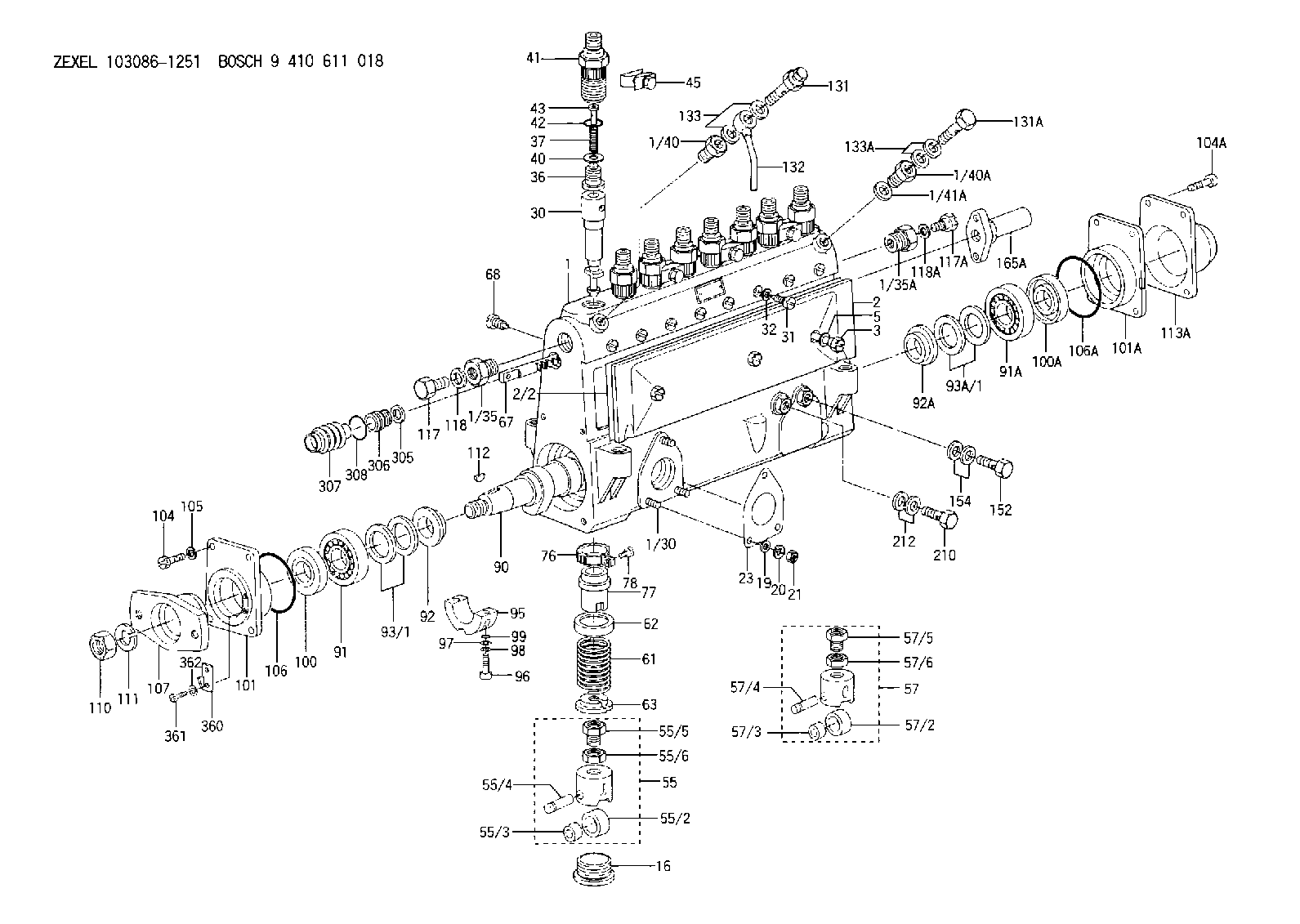
| 1. | [1] | 133051-3920 | PUMP HOUSING |
| 1/30. | [3] | 029040-6020 | STUD |
| 1/35. | [1] | 132400-0900 | ADAPTOR |
| 1/35A. | [1] | 132400-0900 | ADAPTOR |
| 1/40. | [1] | 131423-0200 | ADAPTOR |
| 1/40A. | [1] | 131400-0100 | ADAPTOR |
| 1/41A. | [1] | 026518-2240 | GASKET |
| 2. | [1] | 133010-6820 | COVER |
| 2/2. | [1] | 133011-0500 | GASKET |
| 3. | [3] | 133017-0900 | FLAT-HEAD SCREW |
| 5. | [3] | 029340-8010 | GASKET |
| 16. | [8] | 133034-0400 | CAPSULE |
| 19. | [3] | 029300-6030 | PLAIN WASHER |
| 20. | [3] | 014110-6410 | LOCKING WASHER |
| 21. | [3] | 013020-6020 | UNION NUT |
| 23. | [1] | 133041-0400 | GASKET |
| 30. | [8] | 133151-6820 | PLUNGER-AND-BARREL ASSY Z64 |
| 31. | [8] | 133106-0100 | CAPSULE |
| 32. | [8] | 029330-8110 | GASKET |
| 36. | [8] | 133110-2520 | DELIVERY-VALVE ASSEMBLY Z31 |
| 37. | [8] | 131112-2300 | COILED SPRING |
| 40. | [8] | 134115-0100 | GASKET |
| 41. | [8] | 133116-3200 | FITTING |
| 42. | [8] | 029632-5030 | O-RING |
| 43. | [8] | 131117-2100 | FILLER PIECE |
| 45. | [4] | 133122-1420 | PLATE |
| 55. | [7] | 133200-1420 | TAPPET |
| 55/2. | [7] | 133204-0700 | ROLLER |
| 55/3. | [7] | 133205-0200 | BUSHING |
| 55/4. | [7] | 133203-0300 | BEARING PIN |
| 55/5. | [7] | 133202-0100 | HEXAGON SCREW |
| 55/6. | [7] | 133201-0101 | UNION NUT |
| 57. | [1] | 133200-1620 | TAPPET |
| 57/2. | [1] | 133204-0700 | ROLLER |
| 57/3. | [1] | 133205-0200 | BUSHING |
| 57/4. | [1] | 133203-0300 | BEARING PIN |
| 57/5. | [1] | 133202-0100 | HEXAGON SCREW |
| 57/6. | [1] | 133201-0101 | UNION NUT |
| 61. | [8] | 133215-0600 | COMPRESSION SPRING |
| 62. | [8] | 133216-0100 | SLOTTED WASHER |
| 63. | [8] | 133217-0300 | SLOTTED WASHER |
| 67. | [1] | 133258-1700 | CONTROL RACK |
| 68. | [1] | 132226-0400 | FLAT-HEAD SCREW |
| 76. | [8] | 133240-0100 | PINION |
| 77. | [8] | 133241-0200 | CONTROL SLEEVE |
| 78. | [8] | 131242-0100 | FLAT-HEAD SCREW |
| 90. | [1] | 133380-0700 | CAMSHAFT |
| 91. | [1] | 028223-0010 | BEARING PLATE |
| 91A. | [1] | 016650-3030 | BEARING PLATE |
| 92. | [1] | 133302-0200 | SPACER RING |
| 92A. | [1] | 133302-0100 | SPACER RING |
| 93/1. | [0] | 029313-0010 | SHIM D45&30.2T0.1 |
| 93/1. | [0] | 029313-0020 | SHIM D45&30.2T0.12 |
| 93/1. | [0] | 029313-0030 | SHIM D45&30.2T0.14 |
| 93/1. | [0] | 029313-0040 | SHIM D45&30.2T0.16 |
| 93/1. | [0] | 029313-0050 | SHIM D45&30.2T0.18 |
| 93/1. | [0] | 029313-0060 | SHIM D45&30.2T0.5 |
| 93/1. | [0] | 029313-0070 | SHIM D45&30.2T1 |
| 93A/1. | [0] | 029312-6010 | SHIM D40&26T0.1 |
| 93A/1. | [0] | 029312-6020 | SHIM D40&26T0.12 |
| 93A/1. | [0] | 029312-6030 | SHIM D40&26T0.14 |
| 93A/1. | [0] | 029312-6040 | SHIM D40&26T0.16 |
| 93A/1. | [0] | 029312-6050 | SHIM D40&26T0.18 |
| 93A/1. | [0] | 029312-6060 | SHIM D40&26T0.5 |
| 95. | [1] | 133305-0800 | BEARING SHELL |
| 96. | [2] | 010208-4040 | HEX-SOCKET-HEAD CAP SCREW |
| 97. | [2] | 023500-8120 | PLAIN WASHER |
| 98. | [2] | 023650-8310 | LOCKING WASHER |
| 99. | [2] | 029630-9020 | O-RING |
| 100. | [1] | 029623-0070 | PACKING RING |
| 100A. | [1] | 029622-5010 | PACKING RING |
| 101. | [1] | 133316-4701 | COVER |
| 101A. | [1] | 133316-1300 | COVER |
| 104. | [4] | 029010-8020 | BLEEDER SCREW |
| 104A. | [4] | 021008-2520 | FLAT-HEAD SCREW |
| 105. | [4] | 014110-8440 | LOCKING WASHER D15.4&8.2T2 |
| 106. | [1] | 029637-2000 | O-RING |
| 106A. | [1] | 029637-2000 | O-RING |
| 107. | [1] | 156636-3000 | COUPLING PLATE |
| 110. | [1] | 023012-0040 | UNION NUT |
| 111. | [1] | 014112-0410 | LOCKING WASHER |
| 112. | [1] | 133563-0000 | WOODRUFF KEY |
| 113A. | [1] | 133328-0200 | CAP |
| 117. | [1] | 029111-8010 | CAPSULE M18P1.5L12 |
| 117A. | [1] | 029111-8010 | CAPSULE M18P1.5L12 |
| 118. | [1] | 026518-2240 | GASKET |
| 118A. | [1] | 026518-2240 | GASKET |
| 131. | [1] | 133424-0221 | OVER FLOW VALVE |
| 131A. | [1] | 029731-4570 | EYE BOLT |
| 132. | [1] | 152350-3921 | PIPE |
| 133. | [2] | 029341-4130 | GASKET |
| 133A. | [2] | 029341-4130 | GASKET |
| 152. | [1] | 029731-4080 | EYE BOLT |
| 154. | [2] | 029341-4130 | GASKET |
| 165A. | [1] | 133510-2420 | STOPPING DEVICE |
| 210. | [1] | 134430-0200 | EYE BOLT |
| 212. | [2] | 029341-0110 | GASKET |
| 305. | [1] | 026524-2940 | GASKET |
| 306. | [1] | 133510-2700 | CAP |
| 307. | [1] | 133510-2800 | COVER |
| 308. | [1] | 029632-6030 | O-RING |
| 360. | [1] | 133245-0700 | POINTER |
| 361. | [2] | 010535-0840 | FLAT-HEAD SCREW |
| 362. | [2] | 014110-5440 | LOCKING WASHER |
Cross reference number
Zexel num
Bosch num
Firm num
Name
103086-1251
FUEL-INJECTION PUMP
Q 14BS FUEL INJECTION PUMP PE4-8Z PE
Q 14BS FUEL INJECTION PUMP PE4-8Z PE
Information:
start by:a) disassemble governorb) remove fuel injection pumps 1. Remove cover (1) from the fuel injection pump housing. 2. Remove rack (2) from the fuel injection pump housing. 3. Remove the lifters (3) from the fuel injection pump housing. 4. Put the fuel injection pump housing on end on blocks and use tool (A) to remove snap ring (4) from the camshaft. 5. Use a soft hammer to push the camshaft toward the governor end of the fuel injection pump housing to loosen washer (5) on the camshaft. Remove washer (5). 6. Remove camshaft (6) from the fuel injection pump housing. 7. Remove bearings (7) from the drive end of the fuel injection pump housing. 8. Remove bearings (8) from the governor end of the fuel injection pump housing.Assemble Fuel Injection Pump Housing
Be sure all oil passages are clear and put clean oil on all parts before assembly. 1. Use tooling (A) to install bearing (2) in the governor end of the fuel injection pump housing with junction (joint) (3) toward the top of the fuel injection pump housing. Install the bearing so it is 0.25 0.20 mm (0.10 0.008 in.) below the surface of the housing.2. Use tooling (A) to install bearing (1) in the governor end of the fuel injection pump housing so it is 7.16 0.13 mm (0.282 0.005 in.) below the surface of the housing. 3. Use tooling (A) to install bearing (4) in the drive end of the fuel injection pump housing with the junction (joint) in the bearing toward the top of the fuel injection pump housing. Install the bearing so it is 1.00 0.25 mm (0.039 0.010 in.) below the surface of the housing. 4. Install plate (6) of tooling (C) on the drive end of the fuel injection pump housing to install the bearing for the rack. Use clean grease to hold the new rack bearing on driver (5) of tooling (C). Install the driver and bearing in plate (6) with the groove in the driver in alignment with the pin in the plate and use a hammer to push the bearing into position. The bearing will be installed to the correct depth when the shoulder of the driver is against plate (6).5. Remove tooling (C) from the fuel injection pump housing. The rack bearing must be installed so it is 0.25 0.25 mm (0.010 0.010 in.) below the surface of the housing. 6. Install camshaft (7) in the fuel injection pump housing.7. Put the fuel injection pump housing on end and put a block under the camshaft. 8. Put washer (9) over the end of the camshaft and use tooling (A) and a spacer (8) that has an inside diameter of 38.1 mm (1.5 in.) and a length of 31.75 mm (1.25 in.) to push the washer against its seat on the camshaft. Camshaft must have 0.285 0.235 mm (0.0112 0.0093 in.) end play when washer is pushed against
Be sure all oil passages are clear and put clean oil on all parts before assembly. 1. Use tooling (A) to install bearing (2) in the governor end of the fuel injection pump housing with junction (joint) (3) toward the top of the fuel injection pump housing. Install the bearing so it is 0.25 0.20 mm (0.10 0.008 in.) below the surface of the housing.2. Use tooling (A) to install bearing (1) in the governor end of the fuel injection pump housing so it is 7.16 0.13 mm (0.282 0.005 in.) below the surface of the housing. 3. Use tooling (A) to install bearing (4) in the drive end of the fuel injection pump housing with the junction (joint) in the bearing toward the top of the fuel injection pump housing. Install the bearing so it is 1.00 0.25 mm (0.039 0.010 in.) below the surface of the housing. 4. Install plate (6) of tooling (C) on the drive end of the fuel injection pump housing to install the bearing for the rack. Use clean grease to hold the new rack bearing on driver (5) of tooling (C). Install the driver and bearing in plate (6) with the groove in the driver in alignment with the pin in the plate and use a hammer to push the bearing into position. The bearing will be installed to the correct depth when the shoulder of the driver is against plate (6).5. Remove tooling (C) from the fuel injection pump housing. The rack bearing must be installed so it is 0.25 0.25 mm (0.010 0.010 in.) below the surface of the housing. 6. Install camshaft (7) in the fuel injection pump housing.7. Put the fuel injection pump housing on end and put a block under the camshaft. 8. Put washer (9) over the end of the camshaft and use tooling (A) and a spacer (8) that has an inside diameter of 38.1 mm (1.5 in.) and a length of 31.75 mm (1.25 in.) to push the washer against its seat on the camshaft. Camshaft must have 0.285 0.235 mm (0.0112 0.0093 in.) end play when washer is pushed against