Information fuel-injection pump
BOSCH
9 410 612 947
9410612947
ZEXEL
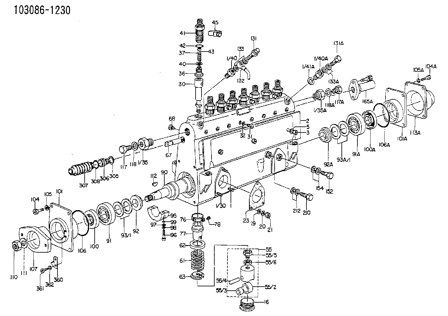
103086-1230
1030861230
Rating:
Scheme ###:
| 1. | [1] | 133051-0920 | PUMP HOUSING |
| 1/30. | [3] | 029040-6020 | STUD |
| 1/35. | [1] | 132400-0900 | ADAPTOR |
| 1/35A. | [1] | 132400-0900 | ADAPTOR |
| 1/40. | [1] | 131423-0200 | ADAPTOR |
| 1/40A. | [1] | 131400-0100 | ADAPTOR |
| 1/41A. | [1] | 026518-2240 | GASKET D21.9&18.2T1 |
| 2. | [1] | 133010-6820 | COVER |
| 2/2. | [1] | 133011-0500 | GASKET |
| 3. | [3] | 133017-0900 | FLAT-HEAD SCREW |
| 5. | [3] | 029340-8010 | GASKET D12&8T1.00 |
| 16. | [8] | 133034-0400 | CAPSULE |
| 19. | [3] | 029300-6030 | PLAIN WASHER D11&6.4T0.5 |
| 20. | [3] | 014110-6410 | LOCKING WASHER |
| 21. | [3] | 013020-6020 | UNION NUT M6P1H5 |
| 23. | [1] | 133041-0400 | GASKET |
| 30. | [8] | 133151-6820 | PLUNGER-AND-BARREL ASSY |
| 31. | [8] | 133106-0100 | CAPSULE |
| 32. | [8] | 029330-8110 | GASKET D13&8.2T1.5 |
| 36. | [8] | 133110-2520 | DELIVERY-VALVE ASSEMBLY |
| 37. | [8] | 131112-2300 | COILED SPRING |
| 40. | [8] | 134115-0100 | GASKET |
| 41. | [8] | 133116-3200 | FITTING |
| 42. | [8] | 029632-5030 | O-RING |
| 43. | [8] | 131117-2100 | FILLER PIECE |
| 45. | [4] | 133122-1420 | PLATE |
| 55. | [8] | 133200-1420 | TAPPET |
| 55/2. | [1] | 133204-0700 | ROLLER |
| 55/3. | [1] | 133205-0200 | BUSHING |
| 55/4. | [1] | 133203-0300 | BEARING PIN |
| 55/5. | [1] | 133202-0100 | HEXAGON SCREW |
| 55/6. | [1] | 133201-0101 | UNION NUT |
| 61. | [8] | 133215-0600 | COMPRESSION SPRING |
| 62. | [8] | 133216-0100 | SLOTTED WASHER |
| 63. | [8] | 133217-0300 | SLOTTED WASHER |
| 67. | [1] | 133258-1700 | CONTROL RACK |
| 68. | [1] | 132226-0400 | FLAT-HEAD SCREW |
| 76. | [8] | 133240-0100 | PINION |
| 77. | [8] | 133241-0200 | CONTROL SLEEVE |
| 78. | [8] | 131242-0100 | FLAT-HEAD SCREW |
| 90. | [1] | 133380-0700 | CAMSHAFT |
| 91. | [1] | 028223-0010 | BEARING PLATE |
| 91A. | [1] | 016650-3030 | BEARING PLATE |
| 92. | [1] | 133302-0200 | SPACER RING |
| 92A. | [1] | 133302-0100 | SPACER RING |
| 93/1. | [0] | 029313-0010 | SHIM D45&30.2T0.1 |
| 93/1. | [0] | 029313-0020 | SHIM D45&30.2T0.12 |
| 93/1. | [0] | 029313-0030 | SHIM D45&30.2T0.14 |
| 93/1. | [0] | 029313-0040 | SHIM D45&30.2T0.16 |
| 93/1. | [0] | 029313-0050 | SHIM D45&30.2T0.18 |
| 93/1. | [0] | 029313-0060 | SHIM D45&30.2T0.5 |
| 93/1. | [0] | 029313-0070 | SHIM D45&30.2T1 |
| 93A/1. | [0] | 029312-6010 | SHIM D40&26T0.1 |
| 93A/1. | [0] | 029312-6020 | SHIM D40&26T0.12 |
| 93A/1. | [0] | 029312-6030 | SHIM D40&26T0.14 |
| 93A/1. | [0] | 029312-6040 | SHIM D40&26T0.16 |
| 93A/1. | [0] | 029312-6050 | SHIM D40&26T0.18 |
| 93A/1. | [0] | 029312-6060 | SHIM D40&26T0.5 |
| 95. | [1] | 133305-0800 | BEARING SHELL |
| 96. | [2] | 020608-4040 | HEX-SOCKET-HEAD CAP SCREW |
| 97. | [2] | 023500-8120 | PLAIN WASHER |
| 98. | [2] | 023650-8310 | LOCKING WASHER |
| 99. | [2] | 029630-9020 | O-RING |
| 100. | [1] | 029623-0010 | PACKING RING |
| 100A. | [1] | 029622-5010 | PACKING RING |
| 101. | [1] | 133316-4701 | COVER |
| 101A. | [1] | 133316-1300 | COVER |
| 104. | [4] | 029010-8020 | BLEEDER SCREW |
| 104A. | [4] | 021008-2520 | FLAT-HEAD SCREW |
| 105. | [4] | 014110-8410 | LOCKING WASHER |
| 105A. | [4] | 014110-8410 | LOCKING WASHER |
| 106. | [1] | 029637-2000 | O-RING |
| 106A. | [1] | 029637-2000 | O-RING |
| 107. | [1] | 156636-3000 | COUPLING PLATE |
| 110. | [1] | 023012-0040 | UNION NUT M20P1.5H16 |
| 111. | [1] | 014112-0410 | LOCKING WASHER |
| 112. | [1] | 133563-0000 | WOODRUFF KEY |
| 113A. | [1] | 133328-0200 | CAP |
| 117. | [1] | 029111-8010 | CAPSULE M18P1.5L12 |
| 117A. | [1] | 029111-8010 | CAPSULE M18P1.5L12 |
| 118. | [1] | 026518-2240 | GASKET D21.9&18.2T1 |
| 118A. | [1] | 026518-2240 | GASKET D21.9&18.2T1 |
| 131. | [1] | 133424-0221 | OVER FLOW VALVE |
| 131A. | [1] | 029731-4570 | EYE BOLT |
| 132. | [1] | 152350-3921 | PIPE |
| 133. | [2] | 029341-4130 | GASKET D20&13.8T2* |
| 133A. | [2] | 029341-4130 | GASKET D20&13.8T2* |
| 152. | [1] | 029731-4680 | EYE BOLT |
| 154. | [2] | 029341-4130 | GASKET D20&13.8T2* |
| 165A. | [1] | 133510-2420 | STOPPING DEVICE |
| 210. | [1] | 134430-0200 | EYE BOLT |
| 212. | [2] | 029341-0110 | GASKET |
| 305. | [1] | 026524-2940 | GASKET D28.9&24.3T2 |
| 306. | [1] | 133510-2700 | CAP |
| 307. | [1] | 133510-2800 | COVER |
| 308. | [1] | 029632-6030 | O-RING |
| 360. | [1] | 133245-0700 | POINTER |
| 361. | [2] | 010535-0840 | FLAT-HEAD SCREW M5P0.8L8 |
| 362. | [2] | 014110-5440 | LOCKING WASHER |
Cross reference number
Zexel num
Bosch num
Firm num
Name
Information:
33. Remove dowels (69) and flyweights (71) from the carrier.34. Remove shaft (70) from the carrier. Remove the dowel from shaft (70). 35. Remove races (72) and bearing (73) from the camshaft in the fuel injection pump housing.Assemble Governor
Put clean oil on all parts before assembly. Be sure all oil passages are clear. 1. Install one race (1), bearing (2) and the other race (1) on the camshaft in the fuel injection pump housing. 2. Put flyweights (3) in position on carrier (4) and install the dowels to hold the flyweights in place. The flyweights must move freely on the dowels and have 0.010 to 0.23 mm (0.0004 to 0.009 in. end play. 3. Install dowel (5) in governor shaft (6) and install the governor shaft in the carrier as shown. 4. Put the carrier in position on the camshaft and install the bolts that hold the carrier in place. Make a replacement of shield (7) any time it is removed.5. Install shield (7) on the carrier and use tool (A) to push the shield against its seat. Use a hammer and punch to move the metal (stake) two places on the side of the shield 180° 5° apart next to the holes in the shield. 6. Install one race (9), bearing (10), the other race (9) and use tool (B) to install the ring on riser (8) as shown. 7. Install riser (8) and spring (overfueling spring) on the governor shaft as shown. 8. Assemble the dashpot as follows:a) Install spring (12) on seat (11) and install seat (13) in spring (12).b) Put spool (14) and ring (15) in position on seat (13) and use tool (B) to install snap ring (16) to hold them in place. 9. Install dashpot assembly (17) on the governor shaft as shown. 10. Install ring (21) in the lower groove in the governor shaft. Install one sleeve (20), spring (19), the other sleeve (20) and bearing (18) on the governor shaft as shown. Spring (19) is used to put a preload on the thrust bearing on the camshaft in the fuel injection pump housing. 11. Use tool (C) to hold spring (19) in compression and install ring (22) in the groove in the governor shaft. Remove tool (C). 12. Put lever (27) in position on governor servo (23) and install pin (24) to hold the lever in place. Use a hammer and chisel to move the metal (stake) four places 90° apart on the outside surface on both legs of the governor servo to hold pin (24) in place.13. Install the O-ring seal on sleeve (25). Install piston (26) and sleeve (25) in the governor servo as shown. 14. Install valve (28) in the governor servo as shown. 15. Install one lockring (32) in the groove near the center of valve (28). Put sleeve (29), spring (broken link spring) (30) and seat (31) in position on valve (28) and install the other lockring (32) to hold them in place. 16.
Put clean oil on all parts before assembly. Be sure all oil passages are clear. 1. Install one race (1), bearing (2) and the other race (1) on the camshaft in the fuel injection pump housing. 2. Put flyweights (3) in position on carrier (4) and install the dowels to hold the flyweights in place. The flyweights must move freely on the dowels and have 0.010 to 0.23 mm (0.0004 to 0.009 in. end play. 3. Install dowel (5) in governor shaft (6) and install the governor shaft in the carrier as shown. 4. Put the carrier in position on the camshaft and install the bolts that hold the carrier in place. Make a replacement of shield (7) any time it is removed.5. Install shield (7) on the carrier and use tool (A) to push the shield against its seat. Use a hammer and punch to move the metal (stake) two places on the side of the shield 180° 5° apart next to the holes in the shield. 6. Install one race (9), bearing (10), the other race (9) and use tool (B) to install the ring on riser (8) as shown. 7. Install riser (8) and spring (overfueling spring) on the governor shaft as shown. 8. Assemble the dashpot as follows:a) Install spring (12) on seat (11) and install seat (13) in spring (12).b) Put spool (14) and ring (15) in position on seat (13) and use tool (B) to install snap ring (16) to hold them in place. 9. Install dashpot assembly (17) on the governor shaft as shown. 10. Install ring (21) in the lower groove in the governor shaft. Install one sleeve (20), spring (19), the other sleeve (20) and bearing (18) on the governor shaft as shown. Spring (19) is used to put a preload on the thrust bearing on the camshaft in the fuel injection pump housing. 11. Use tool (C) to hold spring (19) in compression and install ring (22) in the groove in the governor shaft. Remove tool (C). 12. Put lever (27) in position on governor servo (23) and install pin (24) to hold the lever in place. Use a hammer and chisel to move the metal (stake) four places 90° apart on the outside surface on both legs of the governor servo to hold pin (24) in place.13. Install the O-ring seal on sleeve (25). Install piston (26) and sleeve (25) in the governor servo as shown. 14. Install valve (28) in the governor servo as shown. 15. Install one lockring (32) in the groove near the center of valve (28). Put sleeve (29), spring (broken link spring) (30) and seat (31) in position on valve (28) and install the other lockring (32) to hold them in place. 16.