Information fuel-injection pump
BOSCH
9 410 614 057
9410614057
ZEXEL
103066-3940
1030663940

Rating:
Scheme ###:
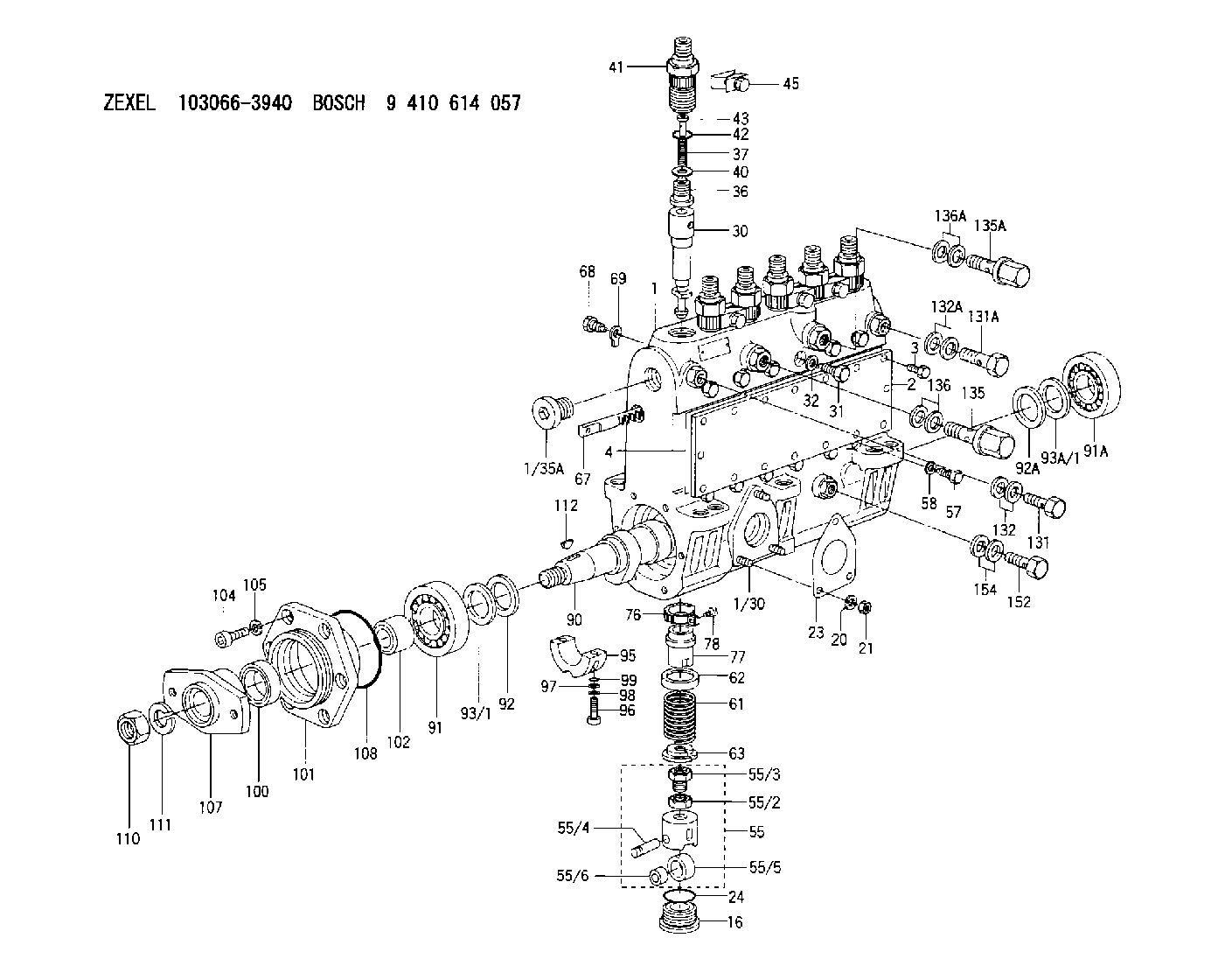
| 1. | [1] | 133051-5720 | PUMP HOUSING |
| 1/30. | [3] | 029040-6020 | STUD |
| 1/35A. | [1] | 029112-4010 | CAPSULE |
| 2. | [1] | 133010-7600 | COVER |
| 3. | [16] | 020106-1440 | BLEEDER SCREW M6P1.0L14 |
| 4. | [1] | 133011-2000 | GASKET |
| 16. | [6] | 133034-0100 | CAPSULE |
| 20. | [3] | 014110-6440 | LOCKING WASHER |
| 21. | [3] | 013020-6040 | UNION NUT M6P1H5 |
| 23. | [1] | 133041-0400 | GASKET |
| 24. | [6] | 029633-4010 | O-RING |
| 30. | [6] | 133151-7420 | PLUNGER-AND-BARREL ASSY |
| 31. | [6] | 133106-0800 | CAPSULE |
| 32. | [6] | 026510-1340 | GASKET D13.4&10.2T1 |
| 36. | [6] | 133110-3120 | DELIVERY-VALVE ASSEMBLY |
| 37. | [6] | 133112-0700 | COILED SPRING |
| 40. | [6] | 133115-1500 | GASKET |
| 41. | [6] | 133116-3520 | FITTING |
| 42. | [6] | 029632-5030 | O-RING |
| 43. | [6] | 134117-0500 | FILLER PIECE |
| 45. | [4] | 133122-1420 | PLATE |
| 55. | [6] | 133200-1220 | TAPPET |
| 55/2. | [1] | 133201-0101 | UNION NUT |
| 55/3. | [1] | 133202-0100 | HEXAGON SCREW |
| 55/4. | [1] | 133203-0400 | BEARING PIN |
| 55/5. | [1] | 133204-0600 | ROLLER |
| 55/6. | [1] | 133205-0300 | BUSHING |
| 57. | [6] | 133210-0400 | FLAT-HEAD SCREW |
| 58. | [6] | 026510-1340 | GASKET D13.4&10.2T1 |
| 61. | [6] | 133215-0900 | COMPRESSION SPRING |
| 62. | [6] | 133216-0200 | SLOTTED WASHER |
| 63. | [6] | 133217-0100 | SLOTTED WASHER |
| 67. | [1] | 133256-4100 | CONTROL RACK |
| 68. | [1] | 133226-0700 | FLAT-HEAD SCREW |
| 69. | [1] | 133516-0400 | TAB WASHER |
| 76. | [6] | 133240-0100 | PINION |
| 77. | [6] | 133241-0200 | CONTROL SLEEVE |
| 78. | [6] | 131242-0100 | FLAT-HEAD SCREW |
| 90. | [1] | 133371-2500 | CAMSHAFT |
| 91. | [1] | 016603-3230 | BEARING PLATE |
| 91A. | [1] | 016603-3230 | BEARING PLATE |
| 92. | [1] | 133302-0200 | SPACER RING |
| 92A. | [1] | 133302-0200 | SPACER RING |
| 93/1. | [0] | 029313-0010 | SHIM D45&30.2T0.1 |
| 93/1. | [0] | 029313-0020 | SHIM D45&30.2T0.12 |
| 93/1. | [0] | 029313-0030 | SHIM D45&30.2T0.14 |
| 93/1. | [0] | 029313-0040 | SHIM D45&30.2T0.16 |
| 93/1. | [0] | 029313-0050 | SHIM D45&30.2T0.18 |
| 93/1. | [0] | 029313-0060 | SHIM D45&30.2T0.5 |
| 93/1. | [0] | 029313-0070 | SHIM D45&30.2T1 |
| 93A/1. | [0] | 029313-0010 | SHIM D45&30.2T0.1 |
| 93A/1. | [0] | 029313-0020 | SHIM D45&30.2T0.12 |
| 93A/1. | [0] | 029313-0030 | SHIM D45&30.2T0.14 |
| 93A/1. | [0] | 029313-0040 | SHIM D45&30.2T0.16 |
| 93A/1. | [0] | 029313-0050 | SHIM D45&30.2T0.18 |
| 93A/1. | [0] | 029313-0060 | SHIM D45&30.2T0.5 |
| 93A/1. | [0] | 029313-0070 | SHIM D45&30.2T1 |
| 95. | [1] | 133306-0200 | BEARING SHELL |
| 96. | [2] | 010208-4040 | HEX-SOCKET-HEAD CAP SCREW |
| 97. | [2] | 023500-8120 | PLAIN WASHER |
| 98. | [2] | 023650-8310 | LOCKING WASHER |
| 99. | [2] | 029630-9020 | O-RING |
| 100. | [1] | 139634-0200 | PACKING RING |
| 101. | [1] | 133316-4800 | COVER |
| 102. | [1] | 134563-2500 | SLIDING PIECE |
| 104. | [6] | 010208-2040 | HEX-SOCKET-HEAD CAP SCREW |
| 105. | [6] | 014110-8440 | LOCKING WASHER |
| 107. | [1] | 156636-1600 | COUPLING PLATE |
| 108. | [1] | 029637-6010 | O-RING |
| 110. | [1] | 023012-0040 | UNION NUT M20P1.5H16 |
| 111. | [1] | 014112-0440 | LOCKING WASHER |
| 112. | [1] | 025806-2210 | WOODRUFF KEY |
| 131. | [1] | 029731-4680 | EYE BOLT |
| 131A. | [1] | 029731-4680 | EYE BOLT |
| 132. | [2] | 029341-4130 | GASKET D20&13.8T2* |
| 132A. | [2] | 029341-4130 | GASKET D20&13.8T2* |
| 135. | [1] | 131425-2020 | OVER FLOW VALVE |
| 135A. | [1] | 131425-2020 | OVER FLOW VALVE |
| 136. | [2] | 029341-4130 | GASKET D20&13.8T2* |
| 136A. | [2] | 029341-4130 | GASKET D20&13.8T2* |
| 152. | [1] | 029731-4680 | EYE BOLT |
| 154. | [2] | 029341-4130 | GASKET D20&13.8T2* |
Cross reference number
Zexel num
Bosch num
Firm num
Name
Information:
Start By:a. remove timing gear case cover1. Put the No. 1 piston at top dead center on the compression stroke. Be sure all the timing marks are in alignment with each other. 2. Remove plate (2) that holds idler gear (1). 3. Remove idler gear (1). 4. Inspect two bushings (3) in idler gear (1). See Engine Specifications for bushing diameter. Remove two bushings (3) if replacement is necessary. 5. Remove fuel injection pump drive gear (4). 6. Bend lock (5) away from the bolt. Remove the bolt and remove washer (6). 7. Remove camshaft drive gear (7) with tool (A).Install Timing Gears
1. Align the slot in gear (1) with the key in the camshaft. Put the camshaft gear in position on the camshaft. 2. Install washer (2), lock (3) and the bolt. Tighten the bolt to a torque of 60-70 N m (45-52 lb ft). Bend the tab of the lock against the bolt head. 3. Align the roll pin in fuel injection pump drive gear (4) with the hole in fuel injection pump drive shaft (5). Install fuel injection pump drive gear (4) on to fuel injection pump drive shaft (5). 4. Install three bolts (6) to hold drive gear (4) to the fuel injection pump drive shaft. 5. Use tool (A) to install two bushings (7) into idler gear (8). Install the bushings even with the outside of idler gear (8). 6. Align the timing marks on idler gear (8) with the crankshaft gear, camshaft drive gear and the fuel injection pump drive gear. 7. Install plate (9) and the bolts to hold idler gear (8) on the idler gear shaft. Tighten the three bolts to a torque of 40 N m (30 lb ft). 8. Check the idler gear end clearance. The clearance must be at least 0.25 mm (.010 in). 9. Fasten a steel plate to the timing gear case. Fasten tooling (A) to the plate as shown. Check the timing gear backlash. The backlash must be 0.08 - 0.15 mm (.003 - .006 in).
1. Align the slot in gear (1) with the key in the camshaft. Put the camshaft gear in position on the camshaft. 2. Install washer (2), lock (3) and the bolt. Tighten the bolt to a torque of 60-70 N m (45-52 lb ft). Bend the tab of the lock against the bolt head. 3. Align the roll pin in fuel injection pump drive gear (4) with the hole in fuel injection pump drive shaft (5). Install fuel injection pump drive gear (4) on to fuel injection pump drive shaft (5). 4. Install three bolts (6) to hold drive gear (4) to the fuel injection pump drive shaft. 5. Use tool (A) to install two bushings (7) into idler gear (8). Install the bushings even with the outside of idler gear (8). 6. Align the timing marks on idler gear (8) with the crankshaft gear, camshaft drive gear and the fuel injection pump drive gear. 7. Install plate (9) and the bolts to hold idler gear (8) on the idler gear shaft. Tighten the three bolts to a torque of 40 N m (30 lb ft). 8. Check the idler gear end clearance. The clearance must be at least 0.25 mm (.010 in). 9. Fasten a steel plate to the timing gear case. Fasten tooling (A) to the plate as shown. Check the timing gear backlash. The backlash must be 0.08 - 0.15 mm (.003 - .006 in).