Information fuel-injection pump
BOSCH
9 410 614 081
9410614081
ZEXEL
103066-3910
1030663910

Rating:
Scheme ###:
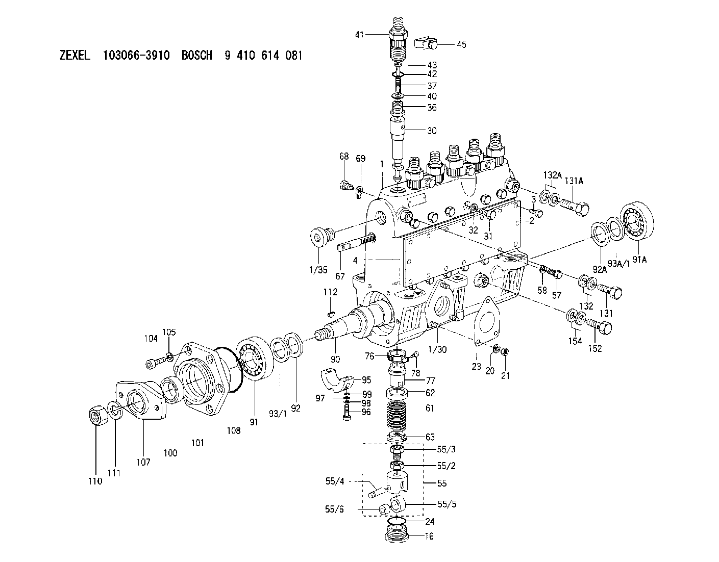
| 1. | [1] | 133051-5520 | PUMP HOUSING |
| 1/30. | [3] | 029040-6020 | STUD |
| 1/35. | [1] | 029112-4010 | CAPSULE |
| 2. | [1] | 133010-7600 | COVER |
| 3. | [16] | 020106-1440 | BLEEDER SCREW M6P1.0L14 |
| 4. | [1] | 133011-2000 | GASKET |
| 16. | [6] | 133034-0100 | CAPSULE |
| 20. | [3] | 014110-6440 | LOCKING WASHER |
| 21. | [3] | 013020-6040 | UNION NUT M6P1H5 |
| 23. | [1] | 133041-0400 | GASKET |
| 24. | [6] | 029633-4040 | O-RING |
| 30. | [6] | 133151-7420 | PLUNGER-AND-BARREL ASSY |
| 31. | [6] | 133106-0800 | CAPSULE |
| 32. | [6] | 026510-1340 | GASKET D13.4&10.2T1 |
| 36. | [6] | 133110-3120 | DELIVERY-VALVE ASSEMBLY |
| 37. | [6] | 133112-0700 | COILED SPRING |
| 40. | [6] | 133115-1500 | GASKET |
| 41. | [6] | 133116-3520 | FITTING |
| 42. | [6] | 029632-5090 | O-RING |
| 43. | [6] | 134117-0500 | FILLER PIECE |
| 45. | [4] | 133122-1420 | PLATE |
| 55. | [6] | 133200-1220 | TAPPET |
| 55/2. | [1] | 133201-0101 | UNION NUT |
| 55/3. | [1] | 133202-0100 | HEXAGON SCREW |
| 55/4. | [1] | 133203-0400 | BEARING PIN |
| 55/5. | [1] | 133204-0600 | ROLLER |
| 55/6. | [1] | 133205-0300 | BUSHING |
| 57. | [6] | 133210-0400 | FLAT-HEAD SCREW |
| 58. | [6] | 026510-1340 | GASKET D13.4&10.2T1 |
| 61. | [6] | 133215-0300 | COMPRESSION SPRING |
| 62. | [6] | 133216-0200 | SLOTTED WASHER |
| 63. | [6] | 133217-0100 | SLOTTED WASHER |
| 67. | [1] | 133256-4100 | CONTROL RACK |
| 68. | [1] | 133226-0700 | FLAT-HEAD SCREW |
| 69. | [1] | 133516-0400 | TAB WASHER |
| 76. | [6] | 133240-0100 | PINION |
| 77. | [6] | 133241-0200 | CONTROL SLEEVE |
| 78. | [6] | 131242-0100 | FLAT-HEAD SCREW |
| 90. | [1] | 133371-2500 | CAMSHAFT |
| 91. | [1] | 016603-3230 | BEARING PLATE |
| 91A. | [1] | 016603-3230 | BEARING PLATE |
| 92. | [1] | 133302-0200 | SPACER RING |
| 92A. | [1] | 133302-0200 | SPACER RING |
| 93/1. | [0] | 029313-0010 | SHIM D45&30.2T0.1 |
| 93/1. | [0] | 029313-0020 | SHIM D45&30.2T0.12 |
| 93/1. | [0] | 029313-0030 | SHIM D45&30.2T0.14 |
| 93/1. | [0] | 029313-0040 | SHIM D45&30.2T0.16 |
| 93/1. | [0] | 029313-0050 | SHIM D45&30.2T0.18 |
| 93/1. | [0] | 029313-0060 | SHIM D45&30.2T0.5 |
| 93/1. | [0] | 029313-0070 | SHIM D45&30.2T1 |
| 93A/1. | [0] | 029313-0010 | SHIM D45&30.2T0.1 |
| 93A/1. | [0] | 029313-0020 | SHIM D45&30.2T0.12 |
| 93A/1. | [0] | 029313-0030 | SHIM D45&30.2T0.14 |
| 93A/1. | [0] | 029313-0040 | SHIM D45&30.2T0.16 |
| 93A/1. | [0] | 029313-0050 | SHIM D45&30.2T0.18 |
| 93A/1. | [0] | 029313-0060 | SHIM D45&30.2T0.5 |
| 93A/1. | [0] | 029313-0070 | SHIM D45&30.2T1 |
| 95. | [1] | 133306-0200 | BEARING SHELL |
| 96. | [2] | 010208-4040 | HEX-SOCKET-HEAD CAP SCREW |
| 97. | [2] | 023500-8120 | PLAIN WASHER |
| 98. | [2] | 023650-8310 | LOCKING WASHER |
| 99. | [2] | 029630-9100 | O-RING |
| 100. | [1] | 139630-0000 | PACKING RING |
| 101. | [1] | 133316-4800 | COVER |
| 104. | [6] | 010208-2040 | HEX-SOCKET-HEAD CAP SCREW |
| 105. | [6] | 014110-8440 | LOCKING WASHER |
| 107. | [1] | 156636-1600 | COUPLING PLATE |
| 108. | [1] | 029637-6020 | O-RING |
| 110. | [1] | 023012-0040 | UNION NUT M20P1.5H16 |
| 111. | [1] | 014112-0440 | LOCKING WASHER |
| 112. | [1] | 025806-2210 | WOODRUFF KEY |
| 131. | [1] | 029731-4680 | EYE BOLT |
| 131A. | [1] | 133424-0420 | OVER FLOW VALVE |
| 132. | [2] | 029341-4130 | GASKET D20&13.8T2* |
| 132A. | [2] | 029341-4130 | GASKET D20&13.8T2* |
| 152. | [1] | 029731-4680 | EYE BOLT |
| 154. | [2] | 029341-4130 | GASKET D20&13.8T2* |
Cross reference number
Zexel num
Bosch num
Firm num
Name
Information:
1. Disconnect electrical plug (1) and throttle linkage (2).2. Disconnect six fuel lines (3) from injection pump. 3. Remove inspection plate (5) from the timing gear cover. 4. Make an alingment of the timing marks on fuel injection pump gear (7) and idler gear (6), or put identification marks on the gears for correct installation. 5. Remove three bolts (8) that hold the fuel injection pump drive gear to the fuel injection pump.
Typical Example6. Put alignment marks on the fuel injection pump and the timing gear case cover as shown. Remove three nuts (9) and washers that hold the fuel injection pump in place. Remove fuel injection pump (10). Remove the gasket from the timing gear case. The following steps are for the installation of the fuel injection pump.7. Put the gasket for fuel injection pump (10) in position on the timing gear case. 8. Position the fuel injection pump; be sure dowel (11) in fuel injection pump gear (7) is in alignment with the groove (slot) in the fuel injection pump shaft when the fuel injection pump is put in position.
Typical Example9. For initial fuel injection pump timing, make an alignment of the reference marks on the fuel injection pump and the timing gear case. Install the three nuts (9) and washers that hold fuel injection pump (10) in place. 10. Be sure the timing marks or the marks that were put on the fuel injection pump gear and idler gear are in alignment. Install three bolts (8) that hold the fuel injection pump gear to the fuel injection pump. 11. Install plate (5) with a new gasket.12 Connect all fuel lines (3), control linkage (2) and electrical plug (1).13. Prime the fuel system. See the MAINTENANCE MANUAL.