Information fuel-injection pump
BOSCH
9 410 612 282
9410612282
ZEXEL
103066-1320
1030661320
Rating:
Scheme ###:
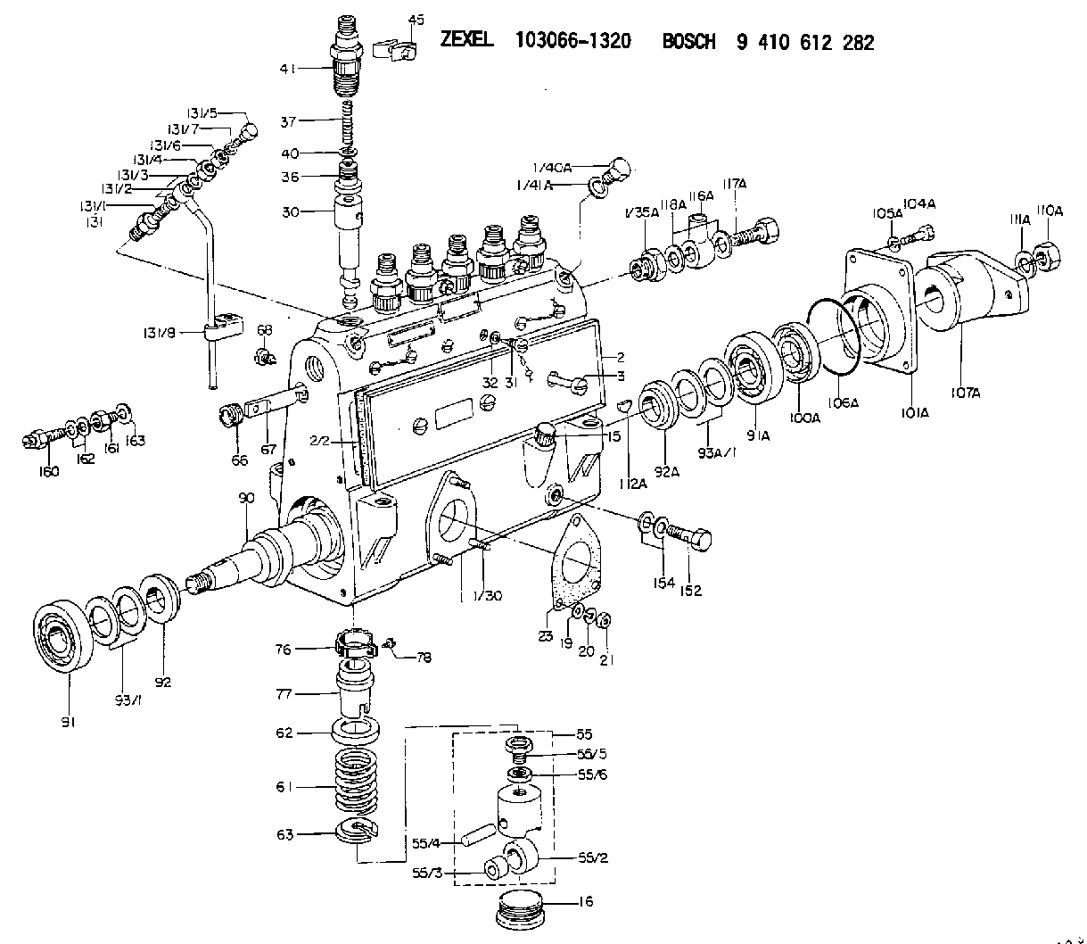
| 1. | [1] | 133050-6520 | PUMP HOUSING |
| 1/30. | [3] | 029040-6020 | STUD |
| 1/35A. | [1] | 132400-0900 | ADAPTOR |
| 1/40A. | [1] | 029111-2090 | CAPSULE |
| 1/41A. | [1] | 026512-1640 | GASKET D15.9&12.2T1 |
| 2. | [1] | 133010-0620 | COVER |
| 2/2. | [1] | 133011-0100 | GASKET |
| 3. | [1] | 133017-0800 | FLAT-HEAD SCREW |
| 15. | [1] | 133030-0120 | LEVEL INDICATOR |
| 16. | [6] | 133034-0400 | CAPSULE |
| 19. | [3] | 029300-6010 | PLAIN WASHER D11&6.4T0.8 |
| 20. | [3] | 014110-6440 | LOCKING WASHER |
| 21. | [3] | 013020-6040 | UNION NUT M6P1H5 |
| 23. | [1] | 133041-0400 | GASKET |
| 30. | [6] | 133101-1120 | PLUNGER-AND-BARREL ASSY |
| 31. | [6] | 133106-0600 | CAPSULE |
| 32. | [6] | 029330-8110 | GASKET D13&8.2T1.5 |
| 36. | [6] | 133110-0120 | DELIVERY-VALVE ASSEMBLY |
| 37. | [6] | 133112-0100 | COMPRESSION SPRING |
| 40. | [6] | 133115-0600 | GASKET |
| 41. | [6] | 133116-1700 | FITTING |
| 45. | [3] | 133122-1420 | PLATE |
| 55. | [6] | 133200-0220 | TAPPET |
| 55/2. | [1] | 133204-0200 | ROLLER |
| 55/3. | [1] | 133205-0200 | BUSHING |
| 55/4. | [1] | 133203-0300 | BEARING PIN |
| 55/5. | [1] | 133202-0100 | HEXAGON SCREW |
| 55/6. | [1] | 133201-0101 | UNION NUT |
| 61. | [6] | 133215-0100 | COMPRESSION SPRING |
| 62. | [6] | 133216-0100 | SLOTTED WASHER |
| 63. | [6] | 133217-0100 | SLOTTED WASHER |
| 66. | [1] | 132222-0100 | BUSHING |
| 67. | [1] | 133256-0000 | CONTROL RACK |
| 68. | [1] | 132226-0400 | FLAT-HEAD SCREW |
| 76. | [6] | 133240-0100 | PINION |
| 77. | [6] | 133241-0200 | CONTROL SLEEVE |
| 78. | [6] | 131242-0100 | FLAT-HEAD SCREW |
| 90. | [1] | 133370-0401 | CAMSHAFT |
| 91. | [1] | 016650-3030 | BEARING PLATE |
| 91A. | [1] | 016650-3030 | BEARING PLATE |
| 92. | [1] | 132302-0100 | SPACER RING |
| 92A. | [1] | 132302-0100 | SPACER RING |
| 93/1. | [0] | 029312-5010 | SHIM D40&25.6T0.12 |
| 93/1. | [0] | 029312-5020 | SHIM D40&25.6T0.14 |
| 93/1. | [0] | 029312-5030 | SHIM D40&25.6T0.16 |
| 93/1. | [0] | 029312-5040 | SHIM D40&25.6T0.18 |
| 93/1. | [0] | 029312-5050 | SHIM D40&25.6T0.5 |
| 93/1. | [0] | 029312-5060 | SHIM D40&25.6T0.2 |
| 93/1. | [0] | 029312-5070 | SHIM D40&25.6T0.3 |
| 93/1. | [0] | 029312-5080 | SHIM D40&25.6T0.4 |
| 93/1. | [0] | 029312-5090 | SHIM D40&25.6T0.1 |
| 93A/1. | [0] | 029312-5010 | SHIM D40&25.6T0.12 |
| 93A/1. | [0] | 029312-5020 | SHIM D40&25.6T0.14 |
| 93A/1. | [0] | 029312-5030 | SHIM D40&25.6T0.16 |
| 93A/1. | [0] | 029312-5040 | SHIM D40&25.6T0.18 |
| 93A/1. | [0] | 029312-5050 | SHIM D40&25.6T0.5 |
| 93A/1. | [0] | 029312-5060 | SHIM D40&25.6T0.2 |
| 93A/1. | [0] | 029312-5070 | SHIM D40&25.6T0.3 |
| 93A/1. | [0] | 029312-5080 | SHIM D40&25.6T0.4 |
| 93A/1. | [0] | 029312-5090 | SHIM D40&25.6T0.1 |
| 100A. | [1] | 029622-5010 | PACKING RING |
| 101A. | [1] | 133316-1700 | COVER |
| 104A. | [4] | 029010-8020 | BLEEDER SCREW |
| 105A. | [4] | 014110-8440 | LOCKING WASHER |
| 106A. | [1] | 029637-2000 | O-RING |
| 107A. | [1] | 156612-5420 | COUPLING PLATE |
| 110A. | [1] | 156023-1800 | UNION NUT |
| 111A. | [1] | 156027-0100 | LOCKING WASHER |
| 112A. | [1] | 025805-1910 | WOODRUFF KEY |
| 116A. | [1] | 029701-8010 | INLET UNION |
| 117A. | [1] | 131601-3900 | BLEEDER SCREW |
| 118A. | [2] | 029331-8050 | GASKET |
| 131. | [1] | 132444-2220 | AIR FILTER |
| 131/1. | [1] | 132441-0200 | SPRING SEAT |
| 131/2. | [1] | 132442-2820 | PIPE |
| 131/3. | [2] | 026512-1540 | GASKET D15.4&12.2T1.50 |
| 131/4. | [1] | 029241-2020 | UNION NUT |
| 131/5. | [1] | 132444-0300 | BLEEDER SCREW |
| 131/6. | [1] | 023020-8040 | UNION NUT M8P1H5 |
| 131/7. | [1] | 026512-1540 | GASKET D15.4&12.2T1.50 |
| 131/8. | [1] | 132447-1800 | CLAMPING BAND |
| 152. | [1] | 029731-0120 | EYE BOLT |
| 154. | [2] | 026510-1450 | GASKET |
| 160. | [1] | 131424-2720 | OVER FLOW VALVE |
| 161. | [1] | 131400-0100 | ADAPTOR |
| 162. | [2] | 026514-1840 | GASKET D17.9&14.2T1 |
| 163. | [1] | 029331-8010 | GASKET |
Cross reference number
Zexel num
Bosch num
Firm num
Name
Information:
This instruction is written for electronic technicians only, and must not be used by service personnel with no training or knowledge of electronics. For repairs that can be done by the Caterpillar Dealer Serviceman, with no knowledge of electronics, see Special Instruction Form SMHS6964 "Using 1P3500 and 2P8280 Injection Timing Groups."As an aid to the technician for troubleshooting the inverter and timing light, the following information is given in this instruction:1. Circuit board illustrations showing the position of each of the components and the test points (T) for using a voltmeter or an oscilloscope.2. Schematics of the electrical circuit so the technician can easily follow the sequence of the circuit.3. Test point values.4. Electrical parts replacement information.5. Timing light calibration procedure.Timing Light
1P3500 And 2P8280 Timing Lights - Electrical Schematic, Test Points And Parts List
Inverter - Electrical Schematic, Test Points And Parts List
There is a two position switch that is marked ADV.-RPM on the side of the 1P3499 Timing Light. When the timing light is in use, operation of the ADV.-RPM switch is as follows:RPM Position
A fuel injection pulse opens the switch in the transducer and starts a positive pulse (TP9) of fixed duration, from the monostable composed of Q2 and Q3. This pulse turns on a transistor switch Q4, allowing current to pass through meter M1, which mechanically averages pulses from an operating engine, and is calibrated to read RPM. Switch S2 grounds the gate of SCR1 to prevent the flash tube from strobing.ADV. Position
A fuel injection pulse again starts a pulse from the monostable. Adjustment of R7, the TIME-ADVANCE control, now determines the pulse duration from the monostable. When R7 is adjusted so that TDC on the damper coincides with the pointer on the block of an operating engine, the monostable pulse duration is exactly the same as the fuel system advance measured in seconds. Transistor switch Q4 again turns on, allowing current to pass through meter M1, causing a meter indicator that is calibrated in degrees of advance instead of seconds.Electrical Calibration Procedure
Before the electrical calibration can be done, the following equipment must be obtained.1) Oscilloscope with triggered sweep. Heath Co. M/N SO-4530 or equivalent.2) Signal generator. Heath M/N SG-72A or equivalent.3) Electronic counter. Data Precision M/N 5740 or equivalent.4) Electronic switch (dealer built).Calibration Procedure
(1) Hold the 1P3499 Timing Light in the same position (about a 45° angle) as if measuring the timing advance on an engine, and check the mechanical meter zero. Make an adjustment to zero if necessary. (2) To remove the protective rubber boot from the flash tube, twist the rubber boot and pull it away from the timing light as shown. (3) Remove the right side (side that has the serial number tag) of the timing light case.(4) Connect the 1P3499 Timing Light to a circuit like the one that follows. This will simulate (be the same as) a fuel flow transducer on an engine that is operating at 2400 RPM. (5) Turn the TIME-ADV. control counterclockwise (CCW) to its minimum